
 Facebook
 Google
 GitHub
 Linkedin
Ladder Logic: It’s Not Just Digital Electrical Prints Anymore
Ladder logic is the legendary industrial graphical programming language that once resembled electrical drawings, but it has advanced far beyond a collection of digital electrical symbols.
In The Beginning, There Were Relays
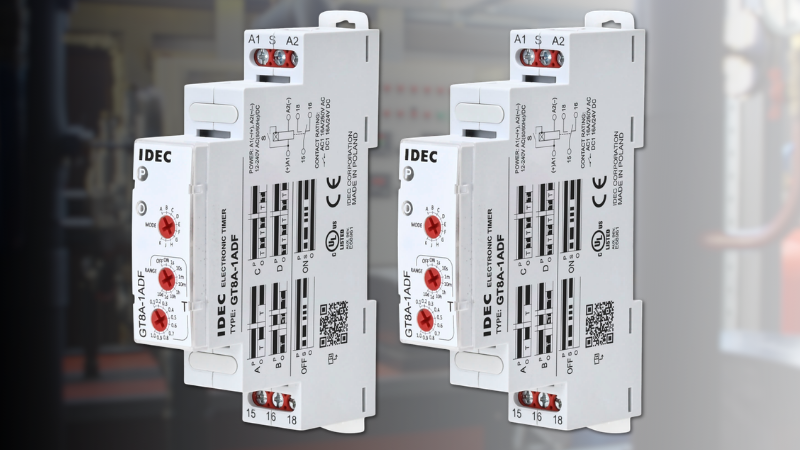
In the early days of automation, mechanical relays controlled outputs. These relays were prone to wear and would malfunction over time. They also consumed a large portion of the electrical cabinet.
The PLC (programmable logic controller) was developed and used ladder logic as its main programming language. This graphical programming language is part of the IEC 61131-3 standard, developed mainly to replace those large cabinets of relays. The instructions used in ladder logic closely resemble electrical drawing symbols, reducing the learning curve for electricians.
Today, ladder logic has developed into an advanced programming language capable of motion control algorithms, handling thousands of inputs and outputs, supporting multiple communication protocols, and allowing programmers to write applications in multiple languages.
In this article, I’ll explore the different ways ladder logic can be used, both simple and complex. I’ll also show that the language has evolved far beyond simple electrical drawings.
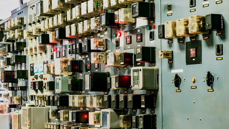
Figure 1. An electrical cabinet with many relays of different types used in power stations. Image used courtesy of Adobe Stock
Simple I/O Control Logic
As mentioned above, the root of ladder logic was developed to replace relays, which is why the same symbols used in electrical drawings are also used in the program.
Take a simple start-stop circuit. A start and stop button are wired to inputs, and a light is wired to an output. When the start button is pressed, the circuit is sealed in by a contact driven by the output, keeping the light output energized until the stop button is pressed. When the stop button is pressed, the circuit is broken, and the light will turn off.

Figure 2. The classic start/stop circuit, popular with relays and with ladder logic. Image used courtesy of the author
If you were to use the same program as a wiring diagram and physically wire buttons, contacts, and relays, you could achieve the same results without a PLC.
So in this example, yes; ladder logic does resemble wiring schematics and could easily be read by most electrical technicians.
Taking It Up a Notch
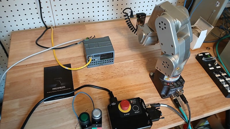
Today’s ladder logic is far more advanced than it used to be. Most programming interfaces have the ability to perform advanced motion control, including coordinated motion, gearing, and virtual axes. Some IDEs also include structured text or even C# in the same routine as the ladder logic. These actions are not possible with relays alone.
Ladder logic happily participates in multiple communication technologies, such as TCP messaging. Most ladder IDEs allow you to open, write, and read TCP sockets to/from other devices on an industrial network.
Sequencing is often a reason for using ladder logic in the first place. Ladder logic often uses built-in sequencers that advance or stop a sequence of customized automated events when receiving specific start, step, and stop signals.
Advanced math functions such as PID calculations, trigonometry, as well as exponents and logarithms can all be used on any rung of a ladder logic program.
None of these features could ever be found on an electrical schematic, and when used with typical logic, can make a program very complex.
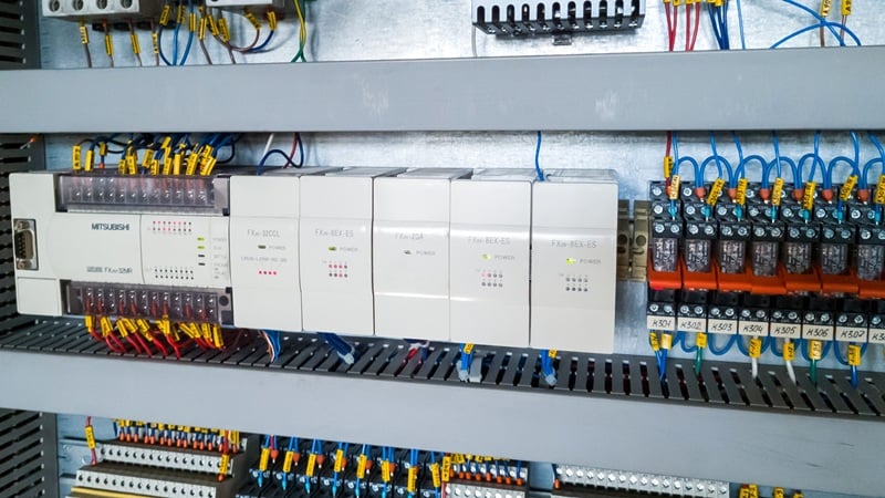
Figure 3. Ladder logic can adapt to projects from basic coils to motion control and network protocols. Image used courtesy of Adobe Stock
Two Styles of Programming
With ladder logic having more functionality than ever before, there is often a desire to make the programs more complex. Using multiple branches and placing outputs in front of inputs makes the code difficult to read and understand. While writing complex ladder logic might be ‘fun’ or written simply to prove that it can go beyond just electrical drawings, it is often not maintainable.
With ladder logic, the application is not compiled, and many other people besides the developer will analyze the code far into the future. With computer software, the developer is often the only one who looks at the code. Once the application is compiled, the user will never see the raw code, so it’s fine if it becomes very complicated.
Control logic needs to be a difficult blend of complex in function, but simple to understand. Sometimes the process you are trying to control is advanced, and the logic driving the process also needs to be complex. Other times you simply need to turn on a light. Writing good control code means your code can be easily read by people who don’t write code every day, yet still be able to automate complex processes.
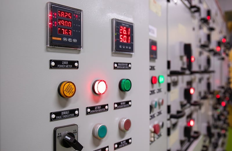
Figure 4. An instrument panel with switches and buttons for operator control. Image used courtesy of Adobe Stock
Not Just an Electrical Print
There was a time when ladder logic was just a digital copy of an electrical schematic, but those days are gone, and now we have the ability to perform motion control, complex math, and advanced communication all from a ladder logic program. Ladder logic does not perform the same as object-oriented programming and requires the developer to think differently when writing in ladder logic. Some of the best ladder programs I’ve worked with are an elegant blend of the complex and simple and do not resemble electrical prints at all.










You give an example of the simple ladder logic program, but not one of the more complex program’s you wrote about. Without a second example this article reads pretty hollow.