 Facebook
 Google
 GitHub
 Linkedin
What is a Signal Conditioner, and Why Do I Need One?
There aren’t actually all that many industrial I/O signal types, and most sensors are designed to output just the right type of signal. But… How do we deal with those pesky potentiometers?
Potentiometers are one of the EE’s favorite old friends. They are simple, and they can be used to control everything from configuring menus to adjusting volume or simply trimming just the right resistance on a sensitive circuit board.
Potentiometers also show up in control systems, and they aren’t always the best of friends for the control engineer.
The Challenge of Potentiometers
First, I’m going to call them ‘pots’ from here on out. Everyone in the EE world calls them pots. Plus, writing out ‘potentiometers’ just feels like an aggressive extension to the article’s character count.
These pots are 3-terminal resistive devices. Supply current enters at terminal 1 and passes through a fixed resistance to terminal 3. Since this is the only resistor in the circuit, it drops all of the source voltage. The resistance value is usually from 1,000 to 50,000 ohms (1-10 kΩ), but you can find all kinds of values.
In the middle, we find terminal 2, which touches the resistor and taps into that voltage drop somewhere along its range. The user can adjust the pot to change where it taps into the voltage, so it may measure any voltage between 0 volts and the source voltage.
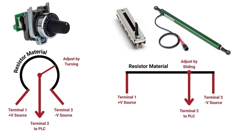
Figure 1. The diagram of a rotary (left) and linear (right) potentiometer.
In a microcontroller application, the source voltage would be either 5 or 3.3 volts, depending on the board. This is perfect because the analog inputs of those microcontrollers also use 0-5 or 0-3.3 volts, respectively.
Industrial power supplies, on the other hand, almost always produce 24 volts, but the analog inputs of PLCs and other industrial controllers do not use that same 0-24 volts. Instead, there are two most common ranges: 0-10 volts and 4-20 mA. (See more info about this; it’s a major topic of discussion.)
The challenge is this: it can be somewhat difficult to convert that 0-24 volt range into 0-10 volts, and very difficult to convert it into 4-20 mA.
Supply Voltage to Analog Input
The premise of this article, as I stated in the title, is about signal conditioners. They are helpful, but before we get to that, let’s discuss the manual circuit methods first.
0-24 Volts → 0-10 Volts
The electrical symbol for a pot is a resistor with an arrow pointing to the middle, and this applies to both linear and rotary pots, no matter the size.
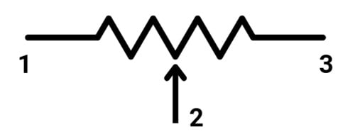
Figure 2. Potentiometer symbol.
The value of the resistor is usually printed on the outside case or in the datasheet. This resistor, if left by itself, will drop the entire source voltage. But in the industrial analog case, we only want it to drop a maximum of up to 10 volts out of the total 24 volts from the supply. This means that we need a second resistor to drop the other 14 volts.
This second resistor can be found using Ohm’s Law, the main principle introduced in your basic DC circuits class.
This potentiometer needs to drop 10 volts. The spec sheet lists it as a 1,000 ohm (1 kΩ) device. To find the amount of current that should pass through it, we use the Ohm’s Law equation:
$$ I = \frac{V}{R} $$
$$ I = \frac{10~V}{1000~Ω} $$
$$ I = 0.01~Amps,~or~10~mA $$
Now, we need a second series resistor that will also carry that same 10 mA, but will drop 14 of the 24 volts before reaching the pot in the first place. The value of this resistor can be found using the same Ohm’s Law equation:
$$ R = \frac{V}{I} $$
$$ R = \frac{14~V}{0.01~A} $$
$$ R = 1400~Ω,~or~1.4~kΩ $$
This resistance value should be placed in series with the pot. My favorite method is by bridging two adjacent terminal blocks with the new resistor.
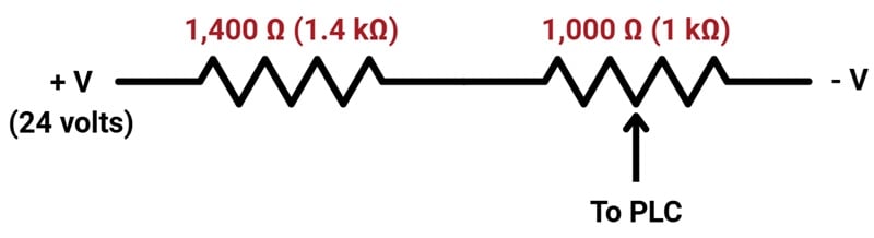
Figure 3. A series circuit for 0-10 volts.
You can purchase 1.4 kΩ resistors, but it’s not a standard 5% value, and the tolerance may lead to some accuracy errors, although it’s probably forgivable.
0-24 Volts → 4-20 mA
Converting a constant voltage signal into constant current is trickier. We must still use Ohm’s Law to determine the total resistance required to supply 4 mA at a minimum:
$$ R = \frac{V}{I} $$
$$ R = \frac{24~V}{0.004~A} $$
$$ R = 6~kΩ $$
The circuit must also provide 20 mA at a maximum:
$$ R = \frac{V}{I} $$
$$ R = \frac{24~V}{0.02~A} $$
$$ R = 1.2~kΩ $$
To accomplish this, we do not have the luxury of choosing any pot that physically fits. We must design a circuit that ranges between 1.2 and 6 kΩ, and that includes the pot. The closest would be to use a 5.0 kΩ pot in series with a 1.2 kΩ fixed resistor
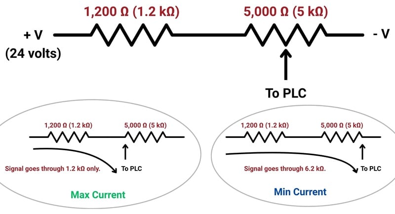
Figure 4. The closest match to 4-20 mA.
This will probably be an acceptable circuit for general rough controls. However, notice that using this resistor combination, the max resistance is 6.2 kΩ. This means that, while we will reach 20 mA at a maximum, turning the dial completely down will reach about 3.9 mA, which exceeds the lowest threshold by just a bit.
If we tried to compensate for this by using a 1.0 kΩ resistor, then the max current would reach 24 mA, which exceeds the maximum threshold. No matter what we choose, we cannot easily design a consistent 4-20 mA circuit.
Finally, the Signal Conditioner
Took about 900 words just to see why this is a problem.
Now, the simple solution: a signal conditioner.
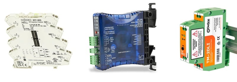
Figure 5. Several typical signal conditioners.
The concept of a signal conditioner is to accept input signals of various types. In this context, we’re discussing the 0-24 volt input of a potentiometer, but these devices may handle frequency inputs, AC inputs, thermocouples, potentiometers… You name it, they output an industry-standard voltage or current signal. The downside is a bit higher cost than a resistor and wiring accessories, but the advantage is a full signal range without using a sub-standard backdoor method to save a buck.
The typical conditioner has three segments. First, power is supplied to the module itself. Then, the input is provided as directed. Some inputs are more universal than others; that is, they accept a wider range of device types. Similarly, the output may provide only one type of analog signal, or more.
In most signal conditioners, the input and output configuration is done through DIP switches on the side or under a protective cover.
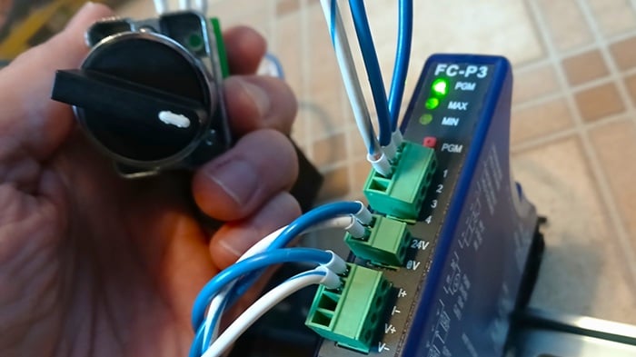
Figure 6. A potentiometer input and 4-20 mA output; tested and verified.
Analog I/O: This is Where the Fun Begins
If you’ve only worked with digital I/O, analog may seem confusing. But once you begin diving into the world of variable signals, you start learning industrial protocols, and the entire control world opens up. So go ahead, go try some new stuff!
All images used courtesy of the author