Cyclogram to Ladder Program

Hi
I'm new on this forum, so please for indulgence.
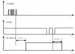
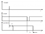
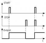
I attend university and in this semester I have subject about PLC programming. This topic is brand new for me and I have only basis about BOOL logic. By the end of the semester we are obliged to do few tasks whose are all about cyclograms and ladder logic (cyclograms->ladder) (example attach: Write a program that implements a latch with a start priority - few combinations).
So here are my questions. Can you give me some links to tutorials, solved examples where I can find step by step how to convert it to the ladder program? Or write even one example, step by step with explanation to my case?
I have been searching for hours internet to find stuff like that, well explained but I didn't find anything clear and specific.

Thank you in advance for any help and please for understanding.
 

Attachments

That looks like a standard SR Flip Flop. There are many ways to implement that in a PLC. Especially since this is a learning exercise, how about you take a crack at it and re-post your code with specific questions where you're stuck.
 
Looks like a Flip-Flop, but also a simple start/stop circuit.

For beginners, for me it has always been the standard traffic light which has a simple sequence to work out.
If you are University material, rather than search for solved examples, you will learn quicker by trial and error; and there are numerous packages where you can run the software without resorting to PLC hardware.
I don't think that trial and error method is OK, because I need to understand the mechanism of ladder and cyclograms. Moreover we have to solve more similar tasks but they're about: Write a program (one) that implements the following cyclogram. So the trial and error method won't work (attachment) and individual project. Sorry If I am wrong but I am pure beginner=dumb so I have to understand these. From my experience when I see few step by step examples and understand the method everything become like piece of cake.
 

Attachments

Trial and error is a way of life, really. In the engineering world, we call it prototyping. You have a concept in mind, run the calculations and simulations as best you can to refine it, then you build it to see if it really works. There will be changes at every step of the process, unless it's a super simple thing (with the concept of "super simple" being different for engineers with different levels of experience).

Your instruction and course materials should be set up so that you can learn step by step the fundamentals rather than just "here's a problem; figure it out." As you progress through the class, they should be explaining enough at each stage to complete the projects.

The best PLC training I've received didn't just explain concepts but also provided opportunities for hands-on programming and experimenting. To try out logic "live" without hardware on hand, here's a fairly simple simulator that I've found to be useful:
https://www.plcfiddle.com/
 
I believe I see the op’s problem - no experience of electrical/electronic engineering, just a bit of logic experience.

To write PLC software, you need to know exactly how the PLC performs; more important you need to know exactly how each machine works that you are controlling. And as most is moving machinery, you need to comply with the EU Machinery Directive (or equivalent elsewhere).

Cyclograms seem to have very little application in control systems, except for perhaps motion control.
Cyclograms in time series analysis look at maps and similar for time dating purposes - a long way from Automation.
 
To write PLC coding you need a little imagination which helps.

Looking at the op’s 2nd diagram:
The Output could be energising a water pump which fills a holding tank. Operation is manual by way of start push button (PB) and stop PB. Polarity of the stop PB is correct for a normally closed contact, giving you active ‘low level’ in the PLC input image table.

After pressing the start PB five times, and after a delay of 2.5 seconds the pump starts. The pump continues to run until the stop PB is pressed twice where after a delay of 2.5 seconds the pump stops. To clarify both buttons perform on the rising edge as opposed to falling edge.

Now before coding this into ladder logic, I would say this is nonsense and ask for clarication.
I have been a many progress meetings with the customer, and because they have told us what they don’t want, I’ve written in basic English as above what the control system will do. Most responses are immediate “NO NO , we don’t want that, it should perform like this ..........” And you have instant progress !
 
Ok, it is important that you learn a way of solving problems.
In my opinion the right way is:
1) write a functional specification that the customer can read, so he can give you feedback on it in his own language. This must not be a technical design description: only talk on functionality: what should it do, when and why.
only when this phase is completely clear:
2) translate the functional specification in a technical specification. In this case it is best to start out with the proven way:
--> translate it into a state machine. It has a starting state and from there it goes to other states based on the input signals (in this case: the start and stop signals)
Each state has a certain combination of the outputs. In this case: your output signal.

This looks like cumbersome and too complex for this, but it is important that you get the principle on how to solve a control problem. Because in the future way more complex problems will cross your path.

Ok, a more or less technical skilled person of the customer can -still- understand your state machine.
Review this state machine. Think of possible input combinations that are not already there.
Think about what it does when it starts in the start state with already some signals in certain conditions.

Remember that there are only states (with certain output combinations), you can only go from 1 state to another one with a certain output combination. And each state has a certain combination of output signals (in your case only 1).

Now, when this is all clear, we will translate it to a SFC in ladder logic.
First: give all your states in the state machine an unique number. State 0 (or 1, what you want) is the starting state number.

3)
Take an integer value for the state number. When it starts it is 0 (or 1, what you want).
In the ladder logic you will define ladders like:
when state number is 0 and input signal x is rising from 0 to 1 and signal y = 0 go to state 10 (for example)
And so on. You define all the transitions from state A to B for all your states.
At the end you will define the output conditions in the ladder:
if state = 0 output Z=1 and output W=0
if state = 10 output xx

and so on.

Now you will have a nice and clear working implementation of the problem.
With a great benefit: it works as it should and does exactly what has been discussed by your customer.

But the biggest benefit: after testing the customer say, yeah it works, but we also need a situation when this or that occurs.
Now you don't have a problem.
Just add the new state+state transitions and implement it into the ladder.

This way you can service the software of the machine for many years to come.

Maybe I already explained too much.......keep us informed on your progress and what your teacher thinks about it.
 
You might say my description above could be a small part of a Functional Description ...
My conclusion is that Cyclograms and specifically ladder logic are really, not entirely compatible.

There must be hundreds of examples where PLC's perform a function which isn't covered
by Cyclograms, which makes we wonder what the University is trying to achieve.

Translating Cyclograms into SFC or Flowchart seems a far more tangible solution
 
Yeah, you know how many youngsters are these days............
They want to learn monkey-tricks.
But they have to learn a way of logical thinking.
The part of getting a functional description 100% right with the customer, is the most important part of all.
They way of implementing that is just some trick.
 
So I would like to continue this thread. Sorry for delay but I had plenty of work when it comes to other subjects.
As the attachment picture shows I have to implement this cyclogram into ladder. I also attach my ladder try. This how I interpret it:
1) press once start (tap button) (stop button is normally closed)
2)after time delay 2s output is on
3)press once stop (tap button)
4)after time delay 3s output is off
So here is my problem, I suppose I have to use TON and TOF timer. But how to place them both? Also how to make it with start and stop tap button. In the second attachment I tried to code it but there is only toggle button and TON timer.
 

Attachments

This is what happens when you are trying to program in fresh air....

What are the working parameters of your TON and TOF timers ? and do you need TOF ?
Rockwell Ton needs retentive i/p to work, so you have to work out how to 'remember' that Start PB has been pressed.
So you first line of logic (in my opinion) has an internal flag {want to start / start pb pressed-stop pb not pressed}.

Simple logic but you have to work out what you are trying to achieve then relate to machine terms.
Study an instruction set because Rockwell ton and Siemens ton operate differently.
 
Top