It's NOT about the number of wires in a multi-core cable--it's how the wires are arranged in the cables in order to reduce the possibility of electrical interference from other wires in the cable, and from other cables, as well.
A "1 pair cable" (to use your description), is most likely also known as a "twisted, shielded pair" cable (often referred to as a TSP cable). In this cable, the two cores are twisted around each other in such a way that the likelihood of induced voltages from nearby cores/cables are more difficult to happen. Further, these twisted cores are usually surrounded by a foil wrapping called the "shield," and there is also usually a bare wire ("core") called the "drain wire" that lays in with the twisted cores and contacts the foil wrapping. The purpose of this foil is to intercept and "capture" any electrical interference, and transmit it to the bare wire. The bare wire is to be grounded (earthed) at one end of the length of the twisted, shielded pair cable thereby "draining" any induced currents (from nearby cores/cables) to earth in one direction (to the single ground/earth connection).
A cable made up of multiple cores without any provision for protecting against electrical interference and induced currents from nearby cores/cables would not protect transmitter signals from being negatively impacted.
MANY people have tried what you are suggesting--a core is a core is a core is a means of transmitting current--for transmitters, and speed sensors, and all manner of low-voltage, low-current control and protection signals. Because, cables designed for such applications are more expensive and need to be properly installed (such as properly grounding/earthing the drain wire at one end of the cable). And, multi-core cables without twisting and shielding are much less expensive and don't require special terminations. And, they have been surprised at the results--VERY surprised, usually. Erratic measurements; unstable processes; nuisance shutdowns and trips which can't be easily troubleshot or explained or eliminated. UNTIL the proper type of cable is installed and properly terminated. And, then--VOILA!!! Suddenly, things seem to run a lot smoother and require less human attention (which is the aim of all automation).
This is a very simple explanation, and if you want more detail--it's certainly available by using your preferred World Wide Web search engine. As with everything technical, it can get VERY complicated and detailed VERY quickly--more-so than you ever thought possible or wanted to imagine.
Suffice it to say: Use the proper cables for the proper applications. And your life will be much simpler and easier.
[NOTE: Some multi-core cables do have a "shield" around untwisted conductors (cores). This is usually done to try to eliminate the amount of electrical interference produced by the current flowing in the cores in the cable--not to prevent electrical interference from affecting the cores in the cable. So, this type of multi-core cables is NOT suitable for transmitters and the like, even though it has "shielding."]
CSA,
Thanks for this explaination. But please i want to know this. If for instance, the bare wire or the drain wire is grounded (earthed) at both ends of the length of the twisted, shielded pair cable, what could be the effect? Anticipating your response. Thank you
If a cable is carrying low-level analog signals, the shield drain wires should be grounded at only one end. Grounding at one end only prevents any current from flowing between non-equipotential ground points, because ground current flowing in the drain wire or shield can couple into the small-signal wires and corrupt the signal. When the drain/shield is connected at only one end, it serves as a Farady cage to isolate the low level signal(s) from noise/interference.
If a cable is carrying low-level analog signals, the shield drain wires should be grounded at only one end. Grounding at one end only prevents any current from flowing between none equipotential ground points, because ground current flowing in the drain wire or shield can couple into the small-signal wires and corrupt the signal. When the drain/shield is connected at only one end, it serves as a Farady cage to isolate the low level signal(s) from noise/interference.
Please, i have an outstanding case i would need help on. It is as below:
CASE
We did an installation about 2 years ago. For overview of how the Control Panel is connected to the Field Instrument, see the attached system layout sketch. After 6 months of the installation and commissioning, we got a report that the system was down and not working anymore. When we got to site, after intensive troubleshooting, we discovered that the 2A fuse was blown, the Surge Protection Device was damaged and some components such as Power diode etc on the Terminal board of the field equipment was also damaged. The communication board was also affected. We did all the necessary repairs and replacement of damaged parts and the system was set into operation again and it was functioning fine.
After 8 months again, we got a report that the system was down again. We went back to site and discovered that the same thing has happened. Even now, the field equipment Power board IC has been affected. We checked the whole system very well, the Panel is well earthed and grounded. Nothing affects the input AC circuit breaker and the Panel switch. Even the power supply unit is very intact.
Please, what could be the problem here and what is likely to be the solution? We really need support here. Thanks in advance for your anticipated response.
David_2,
Please, it is not too clear. Could you make your explanation more clearer. I need to know what could be the actual cause of this problem and how i can solve it once and for all time. Expecting response. Regards
Surge or lightning protection is a whole field in itself. The web site explains some basics of direct strike lightning protection and also mentions that 65% of voltage/current surges are locally produced by switching of electrical loads like motors or heating systems.
For instrumentation, the commercially available surge protection devices can be a module that plugs-in to a DIN mounted wiring terminal block, so that the module can be replaced when the protection device's 'capacity' has been depleted. The big mystery is knowing when the protection is depleted so it can be replaced.
Phoenix Contact even offers an e-learning course on surge protection.
David_2,
Thank you very much for the information. Please, if you were in my shoes, how would you go about solving this problem? I intend to replace the field equipment damaged boards now, replace the fuse and the Surge Protector in the Panel. But to avoid future occurrence of these damages, what can i do or introduce in the panel and the field equipment? Expecting response. Thank you
Um, ..., Er, ..., You didn't even acknowledge whether or not lightning strikes and/or electrical storms may actually exist in the area where this equipment is located.
Further, this query is not even really remotely related to the topic of the original poster.
You should be using twisted, shielded pairs for the connection between the Surge Protector and the Lidar (some 500 metres away). You could probably get away with just using two individual cores for the 24 VDC power supply, but for the RS-485 you need to be using twisted, shielded pair(s)--and the shield drain wire(s) of the pair(s) should be grounded at one end only, and by conventions the shield drain wires should be grounded where the power in the wire originates (so in the Control Panel). The ground should be connected firmly to either functional earth (so-called "control" earth) if it exists at the site, or to protective earth.
There is probably a ground wire for the radar level gauge housing which should be firmly grounded--to protective earth, most likely.
And this is whether--or not--there are electrical storms or lightning strikes in the area which may affect the instrument, cable trays, etc., which should all be firmly grounded to protective earth.
Next, you need to determine where the wires between the Control Room Panel and the radar level gauge are routed. If they are in conduits or cable trays or cable vaults (or something similar) with high voltage wires and cables (anything above 120 VAC, and anything which switches power on and off and that power is 1.0 A or more, especially for higher voltages (above approximately 220 VAC) the interconnecting wire between the Control Room Panel surge protector and the radar level gauge needs to be routed in a different manner and AWAY from the higher voltage/higher current wires (cores) and cables. EVEN IF THERE ARE NOT ELECTRICAL STORMS OR LIGHTNING IN THE AREA WHICH MAY STRIKE OR AFFECT THE EQUIPMENT (most specifically the radar level gauge, and/or the conduit/cable tray which the interconnecting wire is routed through).
MANY people, even some (alleged) technicians, but most usually supervisors and managers, do not want to spend the money required for proper signal level separation--keeping the low-voltage, low-current wires (cores) away from the higher voltage/higher current wires (cores). And, shielding and drain wires DO NOT REPLACE MAINTAINING PROPER SIGNAL LEVEL SEPARATION IN CONDUITS/CABLE TRAYS/CABLE VAULTS, etc. Full stop. Period.
It's possible you're fighting a combination of issues (it happens often)--incorrect shield drain wiring (terminated at both ends instead of just one), improper signal level separation from higher voltage/higher current wires and cables, and maybe even insufficient surge protection. In addition to improperly grounded equipment housing(s), and poor earthing grids. You have to consider it all.
And consider it a learning experience. "Good judgment comes from experience; experience comes from poor judgement." Truer words were never spoken--about technical issues, as well as everyday life. It's just the way it goes. You have to crack some eggs to make a souffle. You can't have your cake, and eat it, too. Into each life a little rain must fall (even in the desert--and when it does rain in the desert, isn't it beautiful--if only for a day or two!).
Best of luck. Please write back to let us know what you found and how you resolved it--at least for now. Another truism is: "The definition of insanity is doing the same--and expecting different results." (Though if a clown gets elected, a circus should be the expected result. Sorry; couldn't resist that.) You've tried something; it didn't work. Doing the same thing isn't going to solve he problem (it doesn't seem like it will, anyway). If you're going to site, you need to look at how it was installed and wired and what could possibly be causing the surge protection to get damaged so quickly. Wiring practices, including signal level separation, and ambient conditions (electrical storms and lightning strikes), and equipment grounding (at the radar level detector, and of the Control Room Panel, and of the shield drain wire(s) (presuming twisted, shielded pair cores were used)).
Again, please write back to let us know how you fare!
CSA,
Thank you immensely for this information and technical analysis. I really appreciate.
Just as you have asked, below are true about the site installations:
1. The cable used is screened, shielded twisted pair cable, 10-cores
2. There are no cable trays used. The cable is piped with PVC pipe and buried from the control room to the tank area, although there is a short distance where it was laid in an open ditch. The buried depth is about 1m.
3. The Drain wire was terminated at both ends. It was terminated at the earth point on the terminal board of the Radar Gauge and also at the earth point of the Panel.
4. The Radar Gauge is earthed to the Tank body at the tank top.
5. A dedicated Earthing system/pit was prepared for the Panel with earth rod and associated stuffs. The 6mm earth cable that runs from the prepared earth pit rod is connected to the marked Earth point in the Panel. That is where the Drain wire of the instrument cable was also connected to.
6. As to whether there was lightning or electrical storms, they couldn't explain.
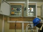
7. Another important thing i would quickly want to mention is that there are 2 different Panels that were installed in the control room side by side as shown in the attached photo . 1 is for the Data Acquisition System which i have sent the sketch already and the other Panel is for Alarm Annunciation. I used 4 pairs, that is 8-cores of the 10-cores twisted pair cable. 4-cores run from the Radar Gauge to the Data Acquisition System Panel and the other 4-cores run from the same Radar Gauge to the Alarm Panel. For the 4-cores that run from the Radar Gauge to the DAS panel, 2-cores are for 24vdc supply to the Radar Gauge while the other 2-cores are for RS 485 communication of the Radar Gauge with the DAS in the Panel. For the other 4-cores, they are connected from the same Radar Gauge to the Alarm Annunciation Panel. Since all these problems have been happening, we have never had any problem with the Alarm Annunciation Panel even up till now. The problem has always been with the DAS panel.
CSA: . . . the shield drain wire(s) of the pair(s) should be grounded at one end only, and by conventions the shield drain wires should be grounded where the power in the wire originates (so in the Control Panel).
Your site: The Drain wire was terminated at both ends. It was terminated at the earth point on the terminal board of the Radar Gauge and also at the earth point of the Panel.
I advocate grounding the drain wire at one end only, preferably at the control panel end.
2. Two panels
Your site: 2 different Panels that were installed in the control room side by side
Are the radar level units supplying discrete signals to the annunciator or are they supplying analog signals that a logic analyzer in the annuciator panel uses to make the decisions on alarms?
David_2,
Thanks for your contribution. As for your question please, find answer below:
Are the radar level units supplying discrete signals to the annunciator or are they supplying analog signals that a logic analyzer in the annuciator panel uses to make the decisions on alarms?
My Answer: The Radar Level Gauge supply Relay Digital Outputs from RL1-RL4 contacts to the Alarm annuciator panel.
Expecting further clarifications please. Thank you
Analog circuit vs discrete circuit damage by surge
It might be that most of my SCADA experience has been with analog signals but I've found in the half dozen near-lightning-strike failures that I've been involved with that the analog signal inputs and/or field devices were destroyed, but in some cases DI inputs for dry contact field sensors (level switches) survived even though they were in the same area and had the same signal routing. I don't know why.
I routinely install an RS-485 isolator to protect the CPU end of a Modbus comm network after a couple situations where quite costly CPUs or comm cards were destroyed by surges (evidence of burned components, traces). If the user will pay for it and there's power available, I'll add multiple isolators along an RS-485 network.
The people I've dealt with could not afford to chase down exact failure modes, all they wanted was their instrumentation and control back up and running, and some wanted to add surge protection for the circuits involved.
I've seen surge protection on 2 wire loop powered field transmitters save a costly field transmitter when the surge protector takes the hit, but sometimes not.
David_2.
Thanks for this further analysis and information.
Now, as a way forward and solution to this recurring problem, you have suggested that the drain wire be grounded at one end preferably at the panel end. That is noted.
But please, what about the power and signal transmission lines? Since the fuse and the Surge Protector SLP32D are always being damaged and even the cards in the gauge being damaged too, what kind of further protective device would you recommend be installed both in the panel and the gauge end so that the system is well protected from lightning strike and other form of surges that can cause havoc to the system?
 Facebook
 Google
 GitHub
 Linkedin
 ath:/caen/web/main/products/technology_pages/subcategory_pages/Surge_protection_e-learning/8a58d320-4cc8-4c3a-8553-8279f411871e