Frame 5 GT loading problem after MI

Good Evening Sir
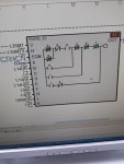
I am working on frame 5 GT (PG5371PA) with mark VIe control system for captive power plant at part load with IGV Exhaust Temp control mode ON.
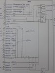
We started our GT after MI and uprate in first week of may. Following control constants were changed by maintenance
TTK_K-63.9 to 65.96
TTK_C- 109.94 to 111.8731
TTK_S- 2.1718 to 2.1478
TTK_M- 2.916 to 2.88
FPKGNG-2.1 to 2.35
FPKGNO- -23.5 to -24

During start up of GT we face following problems-
1. DE was getting de-clutch before 14HA relay Picked up ( we increased DE rpm from 1750 to 1950 and problem solved)
2. DE was getting de-clutch on 51-53 % TNH and starting FSR was shifting "Acc FSR to Temp FSR" and GT was trip on starting device bogged down.
Again we started GT in colder ambient (Early in the morning)and GT successfully reached upto FSNL and we loaded GT.

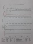
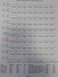
Now during start up of 1.2 MW pump at load 15.9 MW, GT is shifting on base load for 2-2.5 sec
Load- 17.2 MW
CPD-7.40 kscg
CTIM- 37 degree C
IGV- 67.7
FSR-58.6
FSRN-58.6
FSRT-58.6
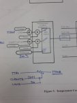
TTRXB-536.7 Degree C
TTXM-524.7 Degree C
TTRX-520 Degree C
TNH-99.4 %
TNR-103.2 %

Please help us to understand the problem
Thanks Again
 
aranrajput1990,

1) Was any new combustion hardware (different design/size fuel nozzles; different combustion liners; different transition pieces) installed during the MI (Major Inspection)?

2) Are the combustors/fuel nozzles conventional, diffusion-flame combustors/nozzles, or DLN-I combustors/fuel nozzles?

3) I presume the unit burns liquid fuel, but ... Please confirm or inform.

4) Mark VIe exhaust temperature Control Constants usually are of the form TTKC_[1], for example, or something similar. The exhaust temperature Control Constants are in an array (meaning that each Control Constant (TTKC, TTKK, TTKI, TTKS, etc.) has eight (8) possible values, so which of the eight values for each of the Control Constants you listed was changed and what were the changes for each of the Control Constants you listed?

5) Was any new turbine section hardware installed during the MI (new design turbine nozzles; new design turbine buckets; new exhaust diffuser; new coatings; etc.)?

Because, it's kind of difficult to understand why the exhaust temperature Control Constants you mentioned were changed if the replacement hardware was the same as what was removed?

6) You mentioned two Control Constants related to gas fuel (FPKGNG, and FPKGNO); does the unit burn natural gas? Or LNG? If the unit is multi-fuel, please list all the fuels the unit burns--AND what fuel is was burning when the start attempts were made.

7) You mentioned ..."exhaust temp control was ON...." CPD- (or CPR-) biased exhaust temperature control is ALWAYS "ON". In fact, it can't be selected OFF (or ON). Are you referring to IGV Exhaust Temperature Control?

8) In my experience, the DE (diesel engine) starting means is almost ALWAYS disengaged before the unit reaches 14HA. 14HA is just there to disengage the starting means if it isn't already disengaged. What is the nameplate rating for the diesel engine RPM?

9) The topic of "hitting" exhaust temperature control during starting, causing bog down and slow acceleration has been covered MANY times on Control.com. It's usually something related to some change in fuel (or, possibly in this case, the change to the P2 pressure reference if the unit runs on gas fuel--the changes to FPKGNG and FPKGNO), OR improper calibration of the GCV LVDT(s) (usually on a GE-design Frame 5 heavy duty gas turbine equipped with a liquid fuel bypass valve or even a variable displacement high-pressure liquid fuel pump there is no LVDT on the liquid fuel control device), OR a problem with the amount of torque the diesel engine is providing (could be diesel engine speed is too low (if the governor was worked on during the MI this could be the problem, or the governor might have loosened and/or moved (if it's a mechanical governor))).

Look, there's a lot wrong with what you wrote and the information you provided. MOSTLY, it's NOT clear at all why the Control Constant changes were made--ANY of them. It's just not "standard practice" to change any Control Constant, much less exhaust temperature Control Constants or P2 pressure reference Control Constants unless there was a hardware change of some sort, OR a fuel change, or a fuel nozzle change, etc. So, you got some 'splaining to do.

Last, you mentioned Iceland. As in the sovereign nation Iceland? Is this unit operating in parallel with other units? If so, how is the frequency controlled (for all the units)? Is there some unit which is operating in Isochronous Speed Control, or is there some "power management system" (often called a PMS) or some kind of frequency control that is used to adjust the speed reference of multiple units operating in parallel in Droop Speed Control mode? If there is some kind of frequency control external to the Mark VIe (which there would need to be in order for it to respond to a load change AND maintain system frequency), or there is something wrong with the "PMS" or load control scheme that caused it not to respond appropriately to the load change.

If you want ANY further help with this thread, you need to provide the answers to ALL the questions--don't forget one (or three); don't skip two (or four); don't ignore any of them. We're NOT THERE beside you. We don't know what you know. We can't see what you see. Help us to help you. By first providing the answers to all the questions above. INCLUDING the question without the number: The one about how the frequency is controlled on the system this unit is providing power to--because if this unit is in Droop Speed Control there MUST be some external control of frequency.

You want answers; so do we. But, you got to clear up some issues first by providing the answers to ALL the questions asked (especially the un-numbered one).

sir, Thanks for reply
we run only one GT for power supply (captive power plant) we are not connected to power grid we operate GT in isochronous speed control to maintain frequency

1. During MI, we replaced fuel nozzles, combustion liners and transition pieces with new one but design was same as earlier.

2. combustors/ nozzles are conventional, diffusion-flame combu
3. NG is the fuel for the GT
4. following control constants were changed
Control Constant old value New value UNIT
TTK_C(0) 109.94 111.8731 psi
TTK_C(1) 114.5798 116.4208 psi
TTK_C(2) 109.94 111.433 psi
TTK_C(3) 109.94 118.6364 psi
TTK_K(0) 63.9 65.96 %
TTK_K(1) 69.6 71.33 %
TTK_K(2) 63.9 65.12 %
TTK_K(3) 63.9 71.9 %
TTK_M(0) 2.916 2.88 F/%
TTK_M(1) 3.204 3.19 F/%
TTK_M(2) 2.916 2.9 F/%
TTK_M(3) 2.916 3.22 F/%
TTK_S(0) 2.172 2.1478 F/psi
TTK_S(1) 2.085 2.0618 F/psi
TTK_S(2) 2.172 2.1481 F/psi
TTK_S(3) 2.172 2.0615 F/psi
TTKGVC 109.94 111.433 psi
TTKGVI 971.6 972 F
TTKGVS 2.1718 2.1481 F/psi
FPKGNG 2.1 2.35
FPKGNO -23.5 -24

5. In MI, Turbine section 1st and 2nd stage buckets, nozzle and shrouds were changed with new. 1st stage shrouds were changed with adbrale coating, 2nd stage shrouds were changed with honey comb shrouds. 2nd stage nozzle and inner barrel were changed with brush seal nozzle and brush seal inner barrel.


6. This unit was design for NG and Naptha fuel but we decommissioned naptha system 09 year ago. now we are operating GT only NG fuel from last 13-14 years


7. by mistake I mentioned it exhaust temp control. It was IGV Temp control mode.

8. It is define in our site that if DE (starting means) dis-engaged before the unit reached 14 HA unit will trip on" starting device Trip" DE rated RPM is 2100.

9. Diesel Engine RPM was low, we replaced 20DA-1 and 20 DA2 and DE rpm increased upto 1950 from 1750 and torque convertor drain orifice dia reduced 7.5 to 6.9mm and problem solved. In MI, no work done on DE and torque convertor.


Thanks again
 
arunrajput1990,

Okay; we're getting somewhere now. Maybe.

It's very likely that the new seals and such installed in the unit allowed for a lightly higher firing temperature (the temperature of the hot gases leaving the first stage turbine nozzles)--so, that's the reason for the changes to the exhaust temperature Control Constants.

As for the P2 pressure reference Control Constants, I have no idea why those were changed.

What is TNK14AH1 and TNK14HA2 at your site? I may have been wrong about the function of 14HA with a diesel engine starting means. It would be necessary to see the application code running in the Mark VIe at your site to understand what happens at your site. And there's not much chance of that happening, wouldn't you agree?

As for the reason why the speed and frequency of the unit dropped when the 1.2 MW motor was started, the Mark VIe was too close to exhaust temperature control when the motor was started. I don't know what the unit is rated at, but you can monitor TTXM and TTRXP and TTRXS and IGV angle (CSGV). When CSGV=CSKGVMAX the IGVs will be at maximum operating angle, which is one of the definitions of operating at Base Load. The other definition is when the actual exhaust temperature (TTXM) equals the exhaust temperature reference (TTTX). When TTXM=TTRX and CSGV=CSKGVMAX, the unit will be at Base Load. If TTXM was just a few degrees short of TTRX and the IGVs were at maximum operating angle and the motor was started, then the unit would go on exhaust temperature control (that is, it would be at Base Load) and it couldn't increase the power output to maintain the frequency when the load increased. We don't know how the unit operated before when it was at the same load with the same ambient conditions and the 1.2 MW motor was started.

I have one suspicion, though. Was the Process Alarm "BACKUP EXHAUST TEMP CONTROL ACTIVE" or some message similar to that? If so, it would indicate EITHER a problem with the new Control Constants, OR, it a problem with GCV LVDT calibration--or a problem introduced by the change in P2 pressure reference.

Before the P2 pressure reference changes, the P2 at 100% speed would have been: ((2.1*100)-23.5=186.5. After the change, the P2 pressure would be: ((2.35*100)-24=211. That means with the same heating value/calorific value of gas fuel the GCV would not be as open as it was before the P2 pressure reference Control Constants were change for the same fuel flow-rate and load (because the pressure ahead of the GCV would be higher for the same fuel flow-rate and load, so the GCV would have to be closed more than it was before for the same fuel flow-rate and load). That could mess up the relationship between the primary and back-up FSR control curves. TTRXP is the primary FSR exhaust temp control curve, and TTRXS is the secondary exhaust temp control curve; TTRX is the lesser of the two. TTRX should always be equal to TTRXP, unless there is something wrong with the CPD transducer(s), in which case the above Process Alarm I suggested would be active AND TTRXP would be greater than TTRXS and TTRX would be equal to TTRXS (not TTRXP).

I'm traveling and trying to switch flights as fast as they keep getting canceled--which isn't easy. That's about all I have time for for now. Maybe next week sometime I can plot the exh temp Control Constants and see what they look like--but YOU can use Trender and make some plots for yourself.

Lastly, I would have to look at the application code in the Mark VIe at your site to understand what the relationship is between TNR and load. I suspect it "interacts" with TNRI--but that's probably a poor suspicion. But, to be sure I'd have to see the application code running in your Mark VIe. I suspect you had GE out to do this modification, but if not you should still be able to tell the provider that you are having problems with exhaust temperature control and they should be able to tell you what data to gather for them (I'm pretty certain that will be their first response, "Get us some more data," without even saying, "Please.") If you have the data I proposed above, in addition to the data you provided you can say, "Here; check your email Inbox and get back to me, please, as soon as possible!"

Best of luck. Please write back to let us know what you find.

Thanks Sir for valuable feedback.....
1. It is define in our control system that TTRX is lesser of TTK_I(968 F), TTRXP and TTRXS. we operate our GT at part load. and IGV follow TTK_I(968 F) because TTRXP and TTRXS is higher than TTK_I.

2. TNK14HA1= 51%
TNK14HA2=47.1%
plz check the attached image for DE Engine starting device trip logic.

3. Before MI, when unit was running, "Back up exhaust temp control alarm" was appearing quickly from alarm to normal and normal to alarm but IGV was following TTK_I because TTK_I was lesser than TTRXP and TTRXS, but TTRXS value was lesser than TTRXP so alarm generated.
this alarm again appear when we started GT after MI. so service provider decided to increase the P2 pressure reference. After this FSR value goes down and TTRXS value exceed to TTRXP and after that "Back up exhaust Temp control active" alarm not appeared.

4. Before MI, when unit was running, during 1.2 MW motor start up, GT never shifted to Base load. This problem comes after MI.

5. Plz check the attached image for TNRV1 block for TNR and load relation.

6. Today again we started 1.2 MW motor and GT again shifted to Base load upto 3 sec. TNR value did not increased as GT load increased. TNR value increased when GT stabilized after loading. Plz check the attached file for trend.

7. we operate GT in Remote mode(Mode Selector). what is the difference between Remote and Auto mode?.
Thanks again
 

Attachments

Thanks Sir for valuable feedback.....
1. It is define in our control system that TTRX is lesser of TTK_I(968 F), TTRXP and TTRXS. we operate our GT at part load. and IGV follow TTK_I(968 F) because TTRXP and TTRXS is higher than TTK_I.

2. TNK14HA1= 51%
TNK14HA2=47.1%
plz check the attached image for DE Engine starting device trip logic.

3. Before MI, when unit was running, "Back up exhaust temp control alarm" was appearing quickly from alarm to normal and normal to alarm but IGV was following TTK_I because TTK_I was lesser than TTRXP and TTRXS, but TTRXS value was lesser than TTRXP so alarm generated.
this alarm again appear when we started GT after MI. so service provider decided to increase the P2 pressure reference. After this FSR value goes down and TTRXS value exceed to TTRXP and after that "Back up exhaust Temp control active" alarm not appeared.

4. Before MI, when unit was running, during 1.2 MW motor start up, GT never shifted to Base load. This problem comes after MI.

5. Plz check the attached image for TNRV1 block for TNR and load relation.

Thanks again
Arunrajput

Thanks for adding datas here.

Could you send a " correct file" I mean Displayed horizontaly for the TNR block.

I tried to open it with another "file viewer ", but it is impossible to read it clearly.

Also on the rung ( that you posted) output signal, is not clear we cannot distinguish "signal name "

I may have some tips , since I have seen such problem on Frame6b DE controls/protection.

ControlsGuy25.
Dear Sir
1. Plz find the attached file for TNR block.

2. L3SMT is the output signal of that rung.

3. As Mr CSA suggest to check the relationship between TNR vs Load. Please find the attached file.

4. I want to know, what is the difference between auto and remote mode(Mode Selector)

Thanks ...
 

Attachments

Dear Sir
1. Plz find the attached file for TNR block.

2. L3SMT is the output signal of that rung.

3. As Mr CSA suggest to check the relationship between TNR vs Load. Please find the attached file.
Thanks ...
Dear Sir

Thank you for this prompt answer.

1.i got to review the file for TNR block and will put comment later.

2.I was pretty sure that Output signal name was L3SMT "STARTING DEVICE TRIP".

When I compare with the frame 6 b code that I got, there is 2 inputs signals added on your Application code rung 23.

L4Y "LOSS OF MASTER PROTECTIVE" & L3SMT"STARTING DEVICE TRIP"( auxiliary contact of the Output coil? ) added in serial . Can you tell us what the purpose of this ?

On my App code for frame 6B again, I got some modifications added due to DE trip .

I can tell you more on this, after you can respond on the asked question.


Also I noticed on the trends that you provided that difference between TNH & TNR is quiet important , one can see How FSRN and FRST are swinging .

Maybe something is not properly tuned/setted in your controls system.

I am sure that CSA, got something to say about that.

Questions:
Why??
What is rated output of the unit (20 MW more or less)??

As you stated we can see Load ( Dwatt ) swinging for a short period of time 3s or 5 s as you mentioned with 1.2MW Motor loaded)

I will have better look on TNR block and get back to you asasp.

You said :
" we operate GT in Remote mode(Mode Selector). what is the difference between Remote and Auto mode?. "

Are you talking about Remote ( control room or DCS )??
They seems quite same, but command signal is coming from DCS for Remote mode as far as i know .


One question on TNR bock:

Are you double checked with the control constants, that they all matching/corresponding with the appopriate values??

We cannot see all " notes left & right of TNR Block document " .

Hope this can help,

Thank you for your feeback!

Controls Guy25.

Good morning sir
1. I have no idea about why L4Y and L3SMT are added in series.

2. Rated output of GT is 22.4 MW at site condition.

3. There are five mode of " mode selector " are define in mark VI control
1. Off mode
2. Crank mode
3. Fire mode
4. Auto mode
5. Remote mode
We run GT in remote mode

4. Yes control constant are checked
 
I want to answer few questions.

the L4Y and L3SMT are in series to latch the signal. Incase the unit trip in starting device will be latched until you reset the unit.

The remote mode is commonly designed for DCS control start. In auto mode you ca start the unit from GE HMI instead of DCS.Auto option is commonly used during commissioning stage.
The rated out put is the deigned output you can achieve from the unit. The supplier should have been told n details during commissioning phase.
But the rated output can be changed or defeated depending on different conditions over the years. That’s some you need to workout from the available documents provided with the package.

Changing the control constant is very very dangerous until it is approved by the machine manufacturer engineering team or done by Authorised machine tuner .

best of luck.
 
Good morning sir
1. I have no idea about why L4Y and L3SMT are added in series.

2. Rated output of GT is 22.4 MW at site condition.

3. There are five mode of " mode selector " are define in mark VI control
1. Off mode
2. Crank mode
3. Fire mode
4. Auto mode
5. Remote mode
We run GT in remote mode

4. Yes control constant are checked
[/QUOTE

Good morning sirs,
arunrajput1990,Kawsar_kuet,


Thank you for your reply.

1.I was pretty sure about L4Y and L3SMT signals but i wanted confirmation .
In the Frame 6B app code, that i got there is no such arrangement on the rung.

There is modification like:
PN signal has been found to drop out occasionally during startup

. This causes L63DM_QDM and L4DE to D.D. and trip.
To overcome this added a 1 sec dropout on L14P1X a new aux to L14P
one for L14P2.
All instances of L14P1 and L14P2 (apart from the coil in PN compar
n named to L14P1X and L14P2X.

Do you have such arrangements , can you check on you app code ?
Is the trip with Starting device solved ??
That may help you !

2.Rated output 22.4MW , where do you see base load reached on the file you sent???
I see load pick at around 17,3 MW when motor loaded, (Is that base load for you ?? )


Is that rather HMI/Mark6e Displaying "BASE LOAD",,,,? when 1.2 MW motor loaded?

Please clarify.

What is the unit behaviour, when connected to grid/facility ?
If operated with grid .

How you operate Unit ? Only "Island mode"?

According to your original post you operate it on Part load (only)??

Nbre of units in your plant? Only one unit ??


Okay i have re-read you original post.

By "Iceland mode " you mean " island mode"?? right ?

Surely you will have to study, closer your unit operating mode !

Something get unclear here, on how to operate unit with "island mode" with "Base load reached ".


There is some doubt to clear, concerning how this unit is operating for sure!

I am sure that CSA will have some comments to add on this thread.

Thank you for your reply ,
ControlsGuy25.
 
I want to answer few questions.

the L4Y and L3SMT are in series to latch the signal. Incase the unit trip in starting device will be latched until you reset the unit.

The remote mode is commonly designed for DCS control start. In auto mode you ca start the unit from GE HMI instead of DCS.Auto option is commonly used during commissioning stage.
The rated out put is the deigned output you can achieve from the unit. The supplier should have been told n details during commissioning phase.
But the rated output can be changed or defeated depending on different conditions over the years. That’s some you need to workout from the available documents provided with the package.

Changing the control constant is very very dangerous until it is approved by the machine manufacturer engineering team or done by Authorised machine tuner .


best of luck.

Thanks for feedback
Dear sir

1. I will comment on this after watching cap.

2. During the motor startup, FSRN value exceed to FSRT so GT status changed to "Base load" from isoch speed.

3. We are not connected to grid. GT is operated for captive power plant. Up to 1.3 MW motors(various motors) are in auto start mode for the process requirement. So we operate GT at part load to margin of stand by motor load.

In our plant, there is two GT, one is in service and another is standby machine (stopped, not in service)

Island means captive power plant, no power backup from grid power.
Dear Sir,

Thank you for this prompt answer.

I will wait for your comment on application code .

Controls Guy25.
 
arunrajput1990,

I'm still traveling, or, rather, trying to.... This pandemic is going to be the death of me, if not for the virus then for the excessive use of my patience and days of my life I will never get back because of canceled flights and re-bookings and sleeping in airports trying to get on the next "available" flight which always seems to get canceled.

a) Anyway, the unit is operated in Isoch Speed Control. It worked "fine" before the MI, and now it's not. (Or was this just a one-time event after the MI (and Control Constant change)?)

b) You haven't told us what the rated load was before the outage. It's a Frame 5 so it should be somewhere around 20-25 MW, but this seems like an older machine so it could be less than 20 MW. The turbine section hardware changes should have helped improve efficiency and power output by reducing hot gas path leakage (the new shrouds and brush seals). I'm sure the supplier gave some estimate of expected, if not guaranteed, performance improvement (either heat rate--which would only be applicable at Base Load at rated speed) or power output.

c) You seem to have some kind of historical data capture and retrieval system. Can you plot FSRN, FSRT, TTRXP, TTRXS, and TTXM for the event under discussion, and attach the plot to a response?

d) AUTO mode is the "local" start/stop/loading mode, local being operation from a GE operator interface by an operator clicking on "buttons" to START, STOP, manually select Governor mode (Isoch or Droop), enable synchronization and control voltage/power factor/VAr output. (Since the unit is operated in Isoch Governor mode, the operator doesn't control load (MW).) REMOTE mode is--usually--a means of enabling another control system to operate the turbine, either manually or via some automated commands (usually load control--which isn't really applicable in this case). Usual types of "REMOTE" control would be from a DCS or Balance of Plant Control system, or AGC (Automatic Governor Control--load control from a distant (geographically) location, such as a dispatch center or grid control headquarters, etc.). Often, plants don't really want to use the GE operator interface--especially when the plant is combined cycle and there are lots of other equipments to be monitored and controlled. So, REMOTE mode allows the DCS, for example, to be used to START and STOP and change load (for units operated in Droop Speed Control) instead of having to move the wheeled operator chair to the GE operator interface to do all things GT-related. For plants, such as peaking plants, that are sometimes unmanned, REMOTE mode is how the plants are operated using discreet signals (usually) for starting and stopping and loading and unloading as necessary. In this case, "remote" means not the GE operator interface, but another control system in the plant, perhaps even in the same room as the Mark*--but NOT the GE operator interface is intended to be used to control the turbine.

When REMOTE mode is selected, usually, the GE operator interface is still capable of being used to control the unit, and the only real difference--usually--is that the inputs from the other control system (such as the DCS) are enabled so that control of the unit can be done from the other ("remote") control system.

So, REMOTE usually means some other means of controlling the GE turbine instead of using the GE operator interface. And, again, usually, REMOTE does not disable the GE operator interface--it just enables the other control system's ability to control the turbine. (Sometimes that's done with discrete inputs (contacts from relays) and analog signals (4-20 mA); other times it's via MODBUS or some other protocol (which requires the GE operator interface to forward the commands to/from the Mark*). Sometimes it's a combination.

Hope this isn't too muddled--but, it's not a straight-forward concept. REMOTE just means another control system is capable of controlling the turbine, in addition to the GE operator interface. Usually. There are (per-)versions of this everywhere, but, generally this is what REMOTE means.

Without more data (the TTRXP, TTRXS, TTRX and TTXM data, specifically) it's difficult to say what happened. I can plot the old and new Control Constants (when I get to a place where I can think and focus on something other that getting home!), but we really need to know how close the unit was to exhaust temp control when the event under discussion occurred. It would also be useful if you can your data archival storage and retrieval system to get the SAME information from operation prior to the MI.... VERY helpful.

You've been able to give us most of what we have asked for. Some questions have gone unanswered, and often times this is because someone thinks the question is irrelevant or unimportant to the discussion. BUT, I can assure you--because we are NOT there alongside you and can't see what you can see, when we ask for information it's because our experience says it will help us to understand what happened or is happening.

Personally, I suspect the Control Constant changes are a large part of the problem--not the entire root cause, but a large contributing factor to the root cause(s). Either that, or, the unit wasn't put back together properly and there is something which is causing the power output to be much lower than it should be, causing the unit to go on exhaust temperature control prematurely.

Along this line of thought, were the CPD transmitter(s) "re-calibrated" during the MI, and if so, are you 100% certain they are properly calibrated? If the unit has atmospheric pressure transmitter(s) (GE device number 96AP-1, and sometimes -2 & -3), are you 100% certain they are working properly and properly calibrated and the sensing lines are all clear and the valves are all open/closed as they should be?

Thanks for your patience. We would truly like to help you resolve this issue, but it is difficult because of the time lag in responses. Work with us, and we will most likely get to the bottom of this.

But, I also think you should have the supplier back to observe the problem(s) and actively participate in the troubleshooting and resolution. This started AFTER their work, which included the Control Constant changes!!!
Dear Sir
I hope now you are at Home and safe.
a). Every time when we start 1 MW motor (or above 1 MW motor) GT shifted to base load. (IGV is not full open, FSRN value exceed to FSRT for 2-3 sec and GT status changed Isoch. speed to Base load).

this time we, observed that when we loaded GT, TNR did not changed, TNR changed when GT stabilized. I request to see this on trend file.

b). Pre-uprate GT output at ISO condition is 20.689 MW and Post- uprate GT output is 22.059 MW at ISO condition.

c). Plz find the attached file for TTRX, TTRXB, TTRXP, TTRXS , TTXM FRST, FSRN. TNR, TNH and D watt trend.
It is define in our system that TTRX is the minimum of TTK_I(520 degree C), TTRXP and TTRXS.

d). Sir Now I am clear about Remote and Auto mode operation.

e). CPD transmitter is properly calibrated. Transmitter and PG (Gauge panel) reading is same. lines are made clear during MI and valve are open condition. CPD is single transmitter and GT has not atmospheric transmitter.

Again Thanks sir for connecting and help to resolve this problem in this pandemic.
 

Attachments

So, from the graphs I have the following observations. But, first this question: Where is the supplier who installed the upgraded seals and shroud blocks--and, I presume, calculated the new exhaust temperature control constants? This problem started after their work, including the Control Constant changes. They should be helping to investigate and resolve this issue--certainly. It would be very interesting to hear what they have to say, and what they are doing about the problem(s).

Also, I have reached home, but I have not had a chance to plot the exhaust temperature Control Constants to see what they look like before and after the MI. (Whomever calculated the new Control Constants should be easily able to do this, very quickly.)

Now to the observations. TTRXS (the back-up, or secondary, exhaust temperature control reference is greater than TTRXP, which is good.

TTRXB is a solid line, which seems a little odd to me. Contrary to popular--and false--belief, TTRXB, as the description states, is the speed-biased exhaust temperature control reference--NOT the Base Load exhaust temperature control bias. The speed bias is sometimes used for temporarily increasing the exhaust temperature control reference, particularly on two-shaft heavy duty gas turbines during starting and acceleration. Sometimes, while breaking the LP shaft away and the IGVs are closed it's helpful to increase the allowable exhaust temperature reference to assist with HP acceleration. But, yours is a single-shaft heavy duty, and I suspect the permissive for temporarily increasing the allowable exhaust temperature control reference is never set to a logic "1" at any time.

DWATT is less than 16 MW, and you claim the new Base Load rating is 22 MW (of course, we don't know what the ambient temperature is at your site; if it's very hot (and I would consider 37 deg C to be at the lower end of pretty warm, approaching hot)) then the actual Base Load will be less than the rated Base Load (I'm presuming the Base Load rating is at 59 deg F, or 15 deg C--but that's just a guess, can you tell us what the nameplate Base Load ambient temperature is?).

The IGV angle is missing from the graph (I know I didn't specifically ask for it, but it wold have been nice to know). I believe you mentioned the unit is normally operated with IGV exhaust temperature control on--which causes the actual exhaust temperature to be very close the exhaust temperature control reference when on, so this is keeping the exhaust temperature high at "part load" to maximize exhaust temperature (usually to produce steam in an HRSG). Can you get similar data including the IGV angle (CSGV) and the IGV reference (CSRGV)? Also, can you look at the app code for the IGV reference and find the signal name for IGV exhaust temperature control (sorry; I can't recall it right now and I don't have any app code to look at) and put it on the graph?

And, this could be a problem I don't think we have discussed--IGV LVDT calibration. If the IGVs are NOT as far open as the Mark VIe believes they are, then that could be a big problem. This would occur if the IGV LVDTs were not properly calibrated, and the calibration was not properly verified after they were "calibrated." Can you confirm that a trained technician or engineer was involved in the IGV LVDT calibration after the MI, AND that a machinist's protractor, or equivalent, was used for calibration AND verification?

The thing for me here is this: TTRXB is higher than TTRX, and neither TTRX nor TTRXB ever changed. (Might just be a different exhaust temperature control block than I have seen before that's causing this.) I suspect TTRX is equal to TTK_I (which I believe you have stated is 968 deg F, or 520 deg F). The odd thing is (for me) is that TTXM is very close to TTRXP, which is kind of expected when IGV exhaust temperature control is on.... BUT, TTRX is less than TTRXB and TTXM was greater than TTRX before the motor started. Which is odd, because, if I recall correctly, TTRXB is the lesser of TTK_I or TTRXP or TTRXS before the speed bias (usually a positive value) is added to arrive at TTRXB, which then becomes TTRX. (Again, this may be a different block than I've seen before, or, I'm just too tired to recall exactly what happens between TTRXB and TTRX--which is very possible after my travels).

When the big motor started, TTRX_B and TTRX did NOT change--they both stayed the same as before the motor started. Hmmm. TTRXS increased, so it did not affect unit operation.

TTRXP DECREASED after the motor started, which makes me think the IGVs opened more as a result of the increased load.

I need to try to find time to calculate the two exhaust temperature references, and I'm going to presume TTK_I (for n=0, n=1, n=2, and n=3).

In the meantime, we need some clarification of IGV LVDT calibration--and don't just say the feedback equals the reference (on the HMI) when using the calibration feature of ToolboxST. If a proper device, used in a proper manner, wasn't used to check IGV angles before and after calibration, then it needs to be done properly--again.

Also, can you provide similar data (I don't think we need to see FSRN or even TNH at this point--but CSGV and CSRGV would be nice, very nice to have)?

AND, what is the supplier doing to help with resolving this problem????
Again thanks sir
Supplier is saying that this is a normal phenomena when a big motor took start. we send the data to them. They will visit to site very soon. We are in touch with them.

a). TTRXB is the TTRX+CSRGVTB(30deg F/ 16.7Deg C)
please check the attached file for TTRX and TTRXB block diagram. This will made all clear about TTRX and TTRXB for our unit.

b).Base load ambient temperature is 15 deg C.

c). Please find the attached file for trend with CSGV(CSRGV trend is not available. CSRGV and CSGV values are same at demand display ) and CTIM.

d). IGV calibrated properly by trained engineer after MI and I crossed verified after calibration by protractor at different angle (42, 56,60,65,70,75,78,80,84 and 86 degree) and found ok.

Thanks Again

d).
 

Attachments

arunrajput1990,

It has been my impression all along that this problem--the one with the unit being unable to accept a 1.0 or 1.2 MW motor starting--only became a problem after the MI (Major Inspection). Please confirm or correct this impression. Was this happening before the MI, too? Or only after the MI? When was the Mark V "upgraded" to a Mark VIe-compatible turbine control system? Before the MI, or during the MI?

I am unfamiliar with the TTRXV5 block you have provided; it's very unusual--to me, anyway. It's not the "normal" way I've seen exhaust temperature control done, but then I haven't seen every version that has ever been used and this is just new to me.

The IGV data indicates the unit is operating on the TTKI_[n] value--which you have provided once above as 968 deg F (520 deg C). (This business of providing some information in SAE unit and some in metric units is frustrating.... Not impossible, but frustrating).

One of the things I'm unclear about is this: TTRXB is approximately 536 deg C, and TTRX is 520 deg C, and TTXM is 520 deg C. I don't understand why they are biasing TTRX with some IGV-related value. What re the values of LSPDB2 and LIGVB and CSRGVTB? (CSRGVTB does not appear to be a Control Constant; is it a calculated value from another block/algorithm?)

That little snippet of TTRXB and the handwritten bit is probably NOT exactly how the TTRXV5 block works. It looks like something which was taken from some manual (maybe pre-Mark V-to-Mark VIe Life Extension upgrade???). So, if that's the case (you are trying to use something from a manual which was provided with the Mark V)--then it's likely it's not too applicable to the Mark VIe.... GE documentation can be pretty bad and confusing and misleading at times. The ONLY "documentation" that really means anything is what's running in the control processor(s) in the turbine control panel. Period. Full stop. Everything else requires logical thinking and analysis to see if it matches the application code (in this case: the TTRXV5 block). And, you would be a VERY LUCKY person if there was Item Help or Block Help in ToolboxST for this block (GE seems to be eliminating the descriptions of many, if not most, of these blocks--which is not good for Customers, technicians--or even their field service personnel). Sorry to be the bearer of this little bit of bad news, but somebody had to do it, apparently.

From the Mark VIe TTRXV5 block snippet you supplied, one can see TTRXP, TTRXS and TTRXB--but those are all outputs from the block. What happens to them AFTER they are output from the block??? I see a 'ttr_min' bit that interacts with a ramp limiter and a comparator and some fault and speed bias logic, but I expect that somewhere in the application code the lesser of TTRXP, TTRXS and TTRXB becomes, ultimately, FSRT.

In my experience in the past what was done was the IGV exhaust temperature control reference temperature was derived from TTRX. I have seen some cases where a small value was subtracted from the TTRX so that the IGVs were always open to TTRX--so that if there was an "event" (like, say, the starting of a large motor when the exhaust temperature (TTXM) was exactly equal to the exhaust temperature control reference (TTRX) because the IGVs were closed and keeping TTXM exactly equal to TTRX there wouldn't be this issue like you are experiencing.

It's pretty clear from the data you provided, that the IGVs opened after the motor started, because TTRXP and TTRXS both decreased, but both were still above TTRX (which is equal to TTKI_[n], 520 deg C, or 968 deg F). Again, the definition of Base Load is when the IGVs are a maximum operating angle (CSKGVMAX, on most units). So, the unit is definitely at Part Load; I can't say why the L30D_B logic went momentarily to "1"--because the IGVs don't appear to have ever gone to maximum operating angle.

Also, I don't ever recall ever monitoring TNR when a GT was operating on Isochronous Speed Control.... So, I'm kind of a little surprised about you "obsession" with TNR in this thread. In my previous experience, there was a TNR (Droop Speed Control) and a TNRI (Isochronous Speed Control) value. To be honest, all I recall was if the operator tried to change load by clicking on RAISE- or LOWER SPEED/LOAD the frequency changed. When the unit is running on Isoch Speed Control, the operator has NO direct control of load--the turbine control will do everything it can to try to maintain speed (frequency) when load changes (motors start or stop or are unloaded or unloaded, electric tea kettles start and stop, Air Conditioners start and stop, etc.). When one tries to change the load of a machine running in Isoch Speed Control, one only succeeds in changing the speed reference--which changes the frequency (reference). If more fuel is put into the turbine than is required for maintaining speed (frequency), it CAN'T get turned into load by the generator. It just becomes speed (frequency)--more fuel equals more speed (equals more frequency); less fuel equals less speed (equals less frequency).

I hate to ask again fir more data (one of GE's FAVORITE requests when they haven't got a friggin' clue what is happening!), but I need to have data with CPD.... I apologize for not asking earlier.

Anyway, I have another question. You have mentioned Iceland. Are daily temperatures as high as 38- or 39 deg C this time of year? (I've only flown through Reykjavik once, and that was literally in the middle of an unexpected snow storm and because the snow plows couldn't keep up with the unusually deep snow that was accumulating in a very short period of time we were delayed leaving for several hours, which didn't upset me too much as the restaurant and salespeople were all very nice and polite). I know this probably doesn't make any difference to the problem at hand, but, I kind of get distracted by these kinds of little things.

Thanks for your patience!
 
Top