Frame 5 GT loading problem after MI

arunrajput1990,

It has been my impression all along that this problem--the one with the unit being unable to accept a 1.0 or 1.2 MW motor starting--only became a problem after the MI (Major Inspection). Please confirm or correct this impression. Was this happening before the MI, too? Or only after the MI? When was the Mark V "upgraded" to a Mark VIe-compatible turbine control system? Before the MI, or during the MI?

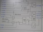
I am unfamiliar with the TTRXV5 block you have provided; it's very unusual--to me, anyway. It's not the "normal" way I've seen exhaust temperature control done, but then I haven't seen every version that has ever been used and this is just new to me.

The IGV data indicates the unit is operating on the TTKI_[n] value--which you have provided once above as 968 deg F (520 deg C). (This business of providing some information in SAE unit and some in metric units is frustrating.... Not impossible, but frustrating).

One of the things I'm unclear about is this: TTRXB is approximately 536 deg C, and TTRX is 520 deg C, and TTXM is 520 deg C. I don't understand why they are biasing TTRX with some IGV-related value. What re the values of LSPDB2 and LIGVB and CSRGVTB? (CSRGVTB does not appear to be a Control Constant; is it a calculated value from another block/algorithm?)

That little snippet of TTRXB and the handwritten bit is probably NOT exactly how the TTRXV5 block works. It looks like something which was taken from some manual (maybe pre-Mark V-to-Mark VIe Life Extension upgrade???). So, if that's the case (you are trying to use something from a manual which was provided with the Mark V)--then it's likely it's not too applicable to the Mark VIe.... GE documentation can be pretty bad and confusing and misleading at times. The ONLY "documentation" that really means anything is what's running in the control processor(s) in the turbine control panel. Period. Full stop. Everything else requires logical thinking and analysis to see if it matches the application code (in this case: the TTRXV5 block). And, you would be a VERY LUCKY person if there was Item Help or Block Help in ToolboxST for this block (GE seems to be eliminating the descriptions of many, if not most, of these blocks--which is not good for Customers, technicians--or even their field service personnel). Sorry to be the bearer of this little bit of bad news, but somebody had to do it, apparently.

From the Mark VIe TTRXV5 block snippet you supplied, one can see TTRXP, TTRXS and TTRXB--but those are all outputs from the block. What happens to them AFTER they are output from the block??? I see a 'ttr_min' bit that interacts with a ramp limiter and a comparator and some fault and speed bias logic, but I expect that somewhere in the application code the lesser of TTRXP, TTRXS and TTRXB becomes, ultimately, FSRT.

In my experience in the past what was done was the IGV exhaust temperature control reference temperature was derived from TTRX. I have seen some cases where a small value was subtracted from the TTRX so that the IGVs were always open to TTRX--so that if there was an "event" (like, say, the starting of a large motor when the exhaust temperature (TTXM) was exactly equal to the exhaust temperature control reference (TTRX) because the IGVs were closed and keeping TTXM exactly equal to TTRX there wouldn't be this issue like you are experiencing.

It's pretty clear from the data you provided, that the IGVs opened after the motor started, because TTRXP and TTRXS both decreased, but both were still above TTRX (which is equal to TTKI_[n], 520 deg C, or 968 deg F). Again, the definition of Base Load is when the IGVs are a maximum operating angle (CSKGVMAX, on most units). So, the unit is definitely at Part Load; I can't say why the L30D_B logic went momentarily to "1"--because the IGVs don't appear to have ever gone to maximum operating angle.

Also, I don't ever recall ever monitoring TNR when a GT was operating on Isochronous Speed Control.... So, I'm kind of a little surprised about you "obsession" with TNR in this thread. In my previous experience, there was a TNR (Droop Speed Control) and a TNRI (Isochronous Speed Control) value. To be honest, all I recall was if the operator tried to change load by clicking on RAISE- or LOWER SPEED/LOAD the frequency changed. When the unit is running on Isoch Speed Control, the operator has NO direct control of load--the turbine control will do everything it can to try to maintain speed (frequency) when load changes (motors start or stop or are unloaded or unloaded, electric tea kettles start and stop, Air Conditioners start and stop, etc.). When one tries to change the load of a machine running in Isoch Speed Control, one only succeeds in changing the speed reference--which changes the frequency (reference). If more fuel is put into the turbine than is required for maintaining speed (frequency), it CAN'T get turned into load by the generator. It just becomes speed (frequency)--more fuel equals more speed (equals more frequency); less fuel equals less speed (equals less frequency).

I hate to ask again fir more data (one of GE's FAVORITE requests when they haven't got a friggin' clue what is happening!), but I need to have data with CPD.... I apologize for not asking earlier.

Anyway, I have another question. You have mentioned Iceland. Are daily temperatures as high as 38- or 39 deg C this time of year? (I've only flown through Reykjavik once, and that was literally in the middle of an unexpected snow storm and because the snow plows couldn't keep up with the unusually deep snow that was accumulating in a very short period of time we were delayed leaving for several hours, which didn't upset me too much as the restaurant and salespeople were all very nice and polite). I know this probably doesn't make any difference to the problem at hand, but, I kind of get distracted by these kinds of little things.

Thanks for your patience!

Good Morning Sir
a). yes This problem comes after MI. We upgraded our control system to mark VIe from mark IV in 2011.

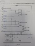
b). I try to explain about TTRXB.
If IGV opening is <76 deg, Then TTRXB=TTRX+CSRGVTB(30 deg F)
If IGV opening is >76 deg Then
CSRGVTB=(CSKGVMAX-CSGV)*3
for Example if IGV opening is 80 degree and TTRX is 968 deg F then
CSRGVTB=(86-80)*3=18 deg F
TTRXB= 968+18= 986 degree F.
After watching CSP, I will share the CSRGVTB algorithm/block.

c). L30D_B logic becomes to "1" when FSR shifted to FSRT in place of FSRN.

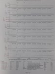
d). For CPD trend please find the attachment.

e). Iceland- this was due to auto spelling correct. I was asking for island unit(captive power plant). at this time of year, ambient temp reaches upto 45 deg C.

f). It is regular activity to change over the 1.0 or 1.2 MW motor at our unit. Today again we started 1 MW motor in droop mode. GT again shifted to base load. this time also TNR did not changes when load increased. (Unfortunate I have no trend for this event).
please mention what parameter you required to resolve this problem. I will share the trend file for next event.

Thanks.
 

Attachments

Arunrajput1990,

a) Does this gas turbine exhaust into an HRSG ("boiler")? Is that why you have IGV exhaust temperature control turned on?

I sincerely doubt I will be able to offer too much more than the supplier of the upgraded hardware and Control Constant changes. I do, more or less, believe that it's not uncommon for the unit to hit CPD-biased exhaust temperature control if IGV exhaust temperature control is active--an important distinction, in my opinion, for a unit being operated in Isoch Speed Control governor mode.

b) Does this unit use Water- or Steam Injection for NOX reduction during operation in Isoch Speed Control governor mode?

I will try to plot some temperature curve data to see if there are any glaring differences between the old- and new Control Constants. But, I have been "given" a last-minute assignment that is going to keep my pretty busy through Thursday (when the deliverable is due).

I really strongly suggest you work closely with the supplier if you haven't already been doing so. If this wasn't an issue before the MI--and the ONLY changes made to what's running in the Mark* were the Control Constant changes, then it's either a hardware issue, OR it's a Control Constant issue. And I doubt we can help much with either of those (unless the plots I'm able to generate show some glaring discrepancy or discontinuity--which the supplier should be able to find, also! the problem is most likely something related to the work done during the MI.

Please keep us posted on the progress--and if this is a constantly occurring issue, or just a one-time thing. One more thing I want to add is I think this unit is being operated pretty close to CPD-biased exhaust temperature control to be expected to respond quickly to large load changes (1.0-1.2 MW is a pretty substantial percentage of rated load, and with IGV exhaust temperature control in operation, the exhaust temperature is already very near the limit (TTRX).) Just my two-and-a-half cents' worth of input
Good Morning All
a). Yes GT exhaust goes to HRSG for steam generation.

b). No such type of arrangement for NOx reduction during the operation.

c). Definitely I will share what we get?

Thanks
 
Arunrajput1990,

Since you seem to run pretty close to Base Load anyway, would you lose that much efficiency/heat rate if you turned of IGV exhaust temperature control--at least as a test--to see what happens when the big motors start and stop?
 
Arunrajput1990,

Since you seem to run pretty close to Base Load anyway, would you lose that much efficiency/heat rate if you turned of IGV exhaust temperature control--at least as a test--to see what happens when the big motors start and stop?
Hello Arunrajput1990,

Could you share , CSRGVTB algorithm/block as you stated before?

I have look on the last trends that you shared, have you reviewed the CSRGVTB algorithm block.

CSA have made clear comments ( same as I would make) on the last trends.

You witnessed/said that there were no changes on TNR value??? Thats someting to inquiry I mean try to review clearly how LOAD controls is done in your App code.

I do not know if constants/values that have been changed are all corrects.

Something( sequence logic/constant values ) may to be corrected for smoother and better operation on this unit.


Thank you for your time and feedback,

ControlsGuy25.
 
ControlsGuy25,

When a single prime mover and synchronous generator are supplying to an "island" load (independent of any other generators or grid) and is being operated in Isochronous Speed Control mode there is no load control. Try to think of riding a bicycle on a long flat road and trying to maintain a constant speed whilst doing so (analogous to a prime mover trying to maintain speed (frequency) on a small grid that is stable and the load is not changing). Pretty easy (I'm presuming a beautiful day, no wind, cool temperature--a pleasant day for a ride at a constant speed).

You have a large basket on the front of your bicycle and as you pass some people on the side of the road someone tosses a heavy package into the basket. What's the first thing that happens? The speed of you and the bicycle starts to decrease (analogous to someone starting a large motor on a small, stable grid). So, you immediately apply more torque to the crankshaft by pedaling harder to increase and return the speed to the desired speed.

In truth, this bicycle analogy is NO different from a prime mover and synchronous generator supplying an isolated load on a small islanded grid. If a large load (such as large motor) is started, the first thing that happens is the speed--and frequency--of the grid, and the generator and prime mover, decreases. The prime mover governor (same as the rider on the bicycle) senses the change in speed (frequency) and increases the fuel to increase the torque being supplied to the generator to return the generator to rated speed (frequency).

It's as simple as that. Full stop. Period.

There is no "load" control to be executed in the governor (the Mark VIe) for the increase in load. The increase in load causes the speed (frequency) to decrease and the governor--because it's in Isoch Speed Control governor mode--says, "NO! I have to increase fuel to return the unit (prime mover and generator) to rated speed (frequency)!!!"

If you, on your bicycle, wanted to carry more weight in the front basket without actually adding more weight by pedaling harder--what would happen? The extra torque from the crankshaft would cause the bicycle speed to increase--because there is, actually, no added weight in the front basket. One can't increase the power being produced by the generator by clicking on a target if there is actually no additional load on the small, stable isolated grid the generator is powering. (Note that when the load is increases when the large motor starts, the load IS seen on the MW meter (or the HMI display)--and the prime mover and generator are actually powering the additional load--but, initially, not at rated speed and frequency. It's not until the governor (the Mark VIe) increases the fuel to return the prime mover and generator speed (frequency) to rated that the frequency goes back to rated--but the load doesn't change when the speed (frequency) increases; it stays the same as when the frequency dropped when the motor was started.

For a machine in Isoch Speed Control governor mode, one can't increase or decrease the amount of power being produced if the load is stable and not changing. Trying to do so will only result in changing the speed (frequency)--which is NOT the same as producing more power, or less power, by changing the reference to the governor (the Mark VIe).

When there's a single synchronous generator supplying a small, isolated load (or loads) an operator or any control system can't change the amount of load being produced (carried, technically) by the generator and its prime mover. The only way to change the load is to increase or decrease the number of motors, or lights, or electric tea kettles, or computers and computer monitors.

I, do agree, that it's entirely possible that some Control Constants are not possibly "tuned" for optimal operation. However, the original poster has said he listed ALL the Control Constants which were changed. What he HASN'T told is what are the Diagnostic Alarms of the Mark VIe when the unit is running, and when this problem is occurring....

And he hasn't told what work was done to the gas fuel control valves (SRV, GCV). Certainly the IGV ring was disassembled and re-assembled. It's possible that something is amiss with the SRV or GCV and not enough fuel can flow fast enough (or as fast as before) to increase the speed when the large motor is started. OR, the IGVs are moving more sluggishly than before and not opening as fast as they should. Either could be the result of a Control Constant change, or, a mechanical problem with the fuel valves and/or their actuators, or the IGVs or its actuator. Which may be indicated by one or more Diagnostic Alarms.
CSA,

My suggestion to Arunrajput1990 is to check the constants in the TNR block ( relation between TNR and Load) .

I agree that there is no "load control" in isochronous mode.

As some parameters have been changed it would be wise to double check all changed parameters.

I will try to give some support on this issue as best as I can.

Controls Guy25.
 
Arunrajput1990,

Since you seem to run pretty close to Base Load anyway, would you lose that much efficiency/heat rate if you turned of IGV exhaust temperature control--at least as a test--to see what happens when the big motors start and stop?
Ok sir
During next motor change over we will try
ControlsGuy25,

When a single prime mover and synchronous generator are supplying to an "island" load (independent of any other generators or grid) and is being operated in Isochronous Speed Control mode there is no load control. Try to think of riding a bicycle on a long flat road and trying to maintain a constant speed whilst doing so (analogous to a prime mover trying to maintain speed (frequency) on a small grid that is stable and the load is not changing). Pretty easy (I'm presuming a beautiful day, no wind, cool temperature--a pleasant day for a ride at a constant speed).

You have a large basket on the front of your bicycle and as you pass some people on the side of the road someone tosses a heavy package into the basket. What's the first thing that happens? The speed of you and the bicycle starts to decrease (analogous to someone starting a large motor on a small, stable grid). So, you immediately apply more torque to the crankshaft by pedaling harder to increase and return the speed to the desired speed.

In truth, this bicycle analogy is NO different from a prime mover and synchronous generator supplying an isolated load on a small islanded grid. If a large load (such as large motor) is started, the first thing that happens is the speed--and frequency--of the grid, and the generator and prime mover, decreases. The prime mover governor (same as the rider on the bicycle) senses the change in speed (frequency) and increases the fuel to increase the torque being supplied to the generator to return the generator to rated speed (frequency).

It's as simple as that. Full stop. Period.

There is no "load" control to be executed in the governor (the Mark VIe) for the increase in load. The increase in load causes the speed (frequency) to decrease and the governor--because it's in Isoch Speed Control governor mode--says, "NO! I have to increase fuel to return the unit (prime mover and generator) to rated speed (frequency)!!!"

If you, on your bicycle, wanted to carry more weight in the front basket without actually adding more weight by pedaling harder--what would happen? The extra torque from the crankshaft would cause the bicycle speed to increase--because there is, actually, no added weight in the front basket. One can't increase the power being produced by the generator by clicking on a target if there is actually no additional load on the small, stable isolated grid the generator is powering. (Note that when the load is increases when the large motor starts, the load IS seen on the MW meter (or the HMI display)--and the prime mover and generator are actually powering the additional load--but, initially, not at rated speed and frequency. It's not until the governor (the Mark VIe) increases the fuel to return the prime mover and generator speed (frequency) to rated that the frequency goes back to rated--but the load doesn't change when the speed (frequency) increases; it stays the same as when the frequency dropped when the motor was started.

For a machine in Isoch Speed Control governor mode, one can't increase or decrease the amount of power being produced if the load is stable and not changing. Trying to do so will only result in changing the speed (frequency)--which is NOT the same as producing more power, or less power, by changing the reference to the governor (the Mark VIe).

When there's a single synchronous generator supplying a small, isolated load (or loads) an operator or any control system can't change the amount of load being produced (carried, technically) by the generator and its prime mover. The only way to change the load is to increase or decrease the number of motors, or lights, or electric tea kettles, or computers and computer monitors.

I, do agree, that it's entirely possible that some Control Constants are not possibly "tuned" for optimal operation. However, the original poster has said he listed ALL the Control Constants which were changed. What he HASN'T told is what are the Diagnostic Alarms of the Mark VIe when the unit is running, and when this problem is occurring....

And he hasn't told what work was done to the gas fuel control valves (SRV, GCV). Certainly the IGV ring was disassembled and re-assembled. It's possible that something is amiss with the SRV or GCV and not enough fuel can flow fast enough (or as fast as before) to increase the speed when the large motor is started. OR, the IGVs are moving more sluggishly than before and not opening as fast as they should. Either could be the result of a Control Constant change, or, a mechanical problem with the fuel valves and/or their actuators, or the IGVs or its actuator. Which may be indicated by one or more Diagnostic Alarms.

Good Evening Sir
You are master in explaining the matter. Well explained about isoch. speed control.
a). when we started the unit I have no alarm history now. we are looking hard copy for that.
b). When we started big motor, every time "Gas fuel intervalve pressure Low " alarm appeared on mark VIe. But on 22.06.2020( 1.0 MW motor started and FSR shifted to FSRT) "Back up ref. Active alarm" with this alarm appear. This alarm appear only once after control constant were changed.
c) SRV/GCV are dis-assembled, re-assembled and calibrated by trained engineer.
d). IGV ring dis-assembled and re-assembled (Blade, gear and ring changed with new)
e). In attachment please find the CSRGVTB block and load regulator module
Thanks
 

Attachments

Hello Arunrajput1990,

Could you share , CSRGVTB algorithm/block as you stated before?

I have look on the last trends that you shared, have you reviewed the CSRGVTB algorithm block.

CSA have made clear comments ( same as I would make) on the last trends.

You witnessed/said that there were no changes on TNR value??? Thats someting to inquiry I mean try to review clearly how LOAD controls is done in your App code.

I do not know if constants/values that have been changed are all corrects.

Something( sequence logic/constant values ) may to be corrected for smoother and better operation on this unit.


Thank you for your time and feedback,

ControlsGuy25.
Good Evening Sir
Please find the attachment for CSRGVTB algorithm/block and load regulator module
 

Attachments

Good Evening Sir
Please find the attachment for CSRGVTB algorithm/block and load regulator module
Good afternoon Sir ,

Could you update us, on the issue you have been faced ?

It would be great if we can have feedback, if issue still occuring or not?

Can you confirm that the control constants for load and CSRGVTB block diagram regulator have been checked and confirmed ?

As soon as we get these informations better we can have study on the last files that you shared.

We do not see what signal name is associated to LGVAPQ signal in top of block ?

I have a 9fa Mark6e app code and there are parameters to be checked and confirmed like dead band parameters and others shwon on the block diagrams .


Again I suggest that Can you check and tune/retune the controls constants .

Thank you for your understanding,

Best regards,
James.
 
Hi, all,

I don't disagree that Control Constants can be tuned to help with some of this, but, the question remains: Why did it start, and only after the MI? And suggesting Control Constants can be "tuned" without suggesting which ones should be tuned and how, well, that's not very helpful. Before changing any other Control Constants--because, reportedly it worked fine BEFORE the MI and configuration changes--we should be trying to eliminate as many mechanical causes as possible, as well as understanding how the new Control Constants might be making the unit behave. Sure; it's probably possible to make some Control Constant changes ("tuning") that will make things "better"--but, are those the right changes to be making, or are they masking some other problem?

I'm still leaning towards the new exhaust temperature control constants being not exactly correct--especially the interaction between primary and back-up exhaust temperature control. That is difficult to plot with MS-Excel, since the two use different x-axes. It's better to plot the actual TTRXS and TTRXP values while the unit is running to see what the interaction is.

As for the P2 pressure low process alarm. That is most likely resulting from the GCV opening very quickly, BUT the SRV isn't able to keep the P2 pressure constant. AND, because P2 pressure is a function of HP shaft speed, when the speed (frequency) decreases that will also drive the P2 pressure reference down, though that shouldn't have too much of an effect resulting in this particular alarm (because if the P2 pressure is low, and the reference drops because the HP speed (frequency) dropped, well then it's kind of a race to see which is the problem isn't it???). In my mind, it sounds like the GCV is opening very quickly, but there's something amiss with the gas fuel supply--either the supply pressure is dropping excessively when the GCV (and SRV) opens because of the load increase, or the gas fuel supply flow-rate is somehow restricted (which might, or might not, always result in low supply pressure--but it usually will, and it also depends on where the supply pressure is monitored/sensed, doesn't it?). It would necessary to see FPRG and FPG2 while the issue was occurring to try to be more precise as to what is happening and why.

I also still believe the site is fighting multiple problems, not just one. It's very possible that the gas valves, having been refurbished, didn't use the exact same internals as were in the valves originally, resulting in some flow differences even though the LVDTs were properly calibrated (which I ALWAYS question when the gas valve assembly is one of the combined assemblies (with both the SRV and GCV in the same housing)). Also, it's entirely possible the same electro-hydraulic servo-valves weren't used when the valves were reinstalled. Also, I have seen the last-chance filters at the hydraulic manifold of the combined gas valve assembly be plugged (chocked; choked) because of dirt in the hydraulic lines which was disturbed during the outage; most times a proper flush isn't done after a maintenance outage and before a re-start. There are lots of possibilities for problems when this much mechanical work was done.

Usually, there is at a minimum a y-strainer, which is really just a "rock-catcher" upstream of the SRV. I have seen those get plugged with debris and cause gas fuel supply restrictions. Or, some sites have a cyclone separator to remove liquids, or some kind of gas fuel supply filter which removes other impurities, smaller than the y-strainer would remove, and which can get plugged (chocked; choked).

Again, I'm interested in actual Process- and Diagnostic Alarm lists. If the unit has a Mark VIe, and the HMI was properly configured, then there should be a folder of historical alarms which is automatically populated and maintained on a rolling period (sometimes as long as one month). This replaces a printed Alarm Report or -Log for most site--but, GE has a horrible problem of not properly configuring the HMIs for this very simple, automatic and NECESSARY function of temporarily storing alarms to an HMI. Also, there should be an automatically uploaded Trip Log or Trip History after every trip in some folder on the HMI, and that can be opened with Trender, and that file also stores a chronological list of Process Alarms, Events and SOEs which is easily accessible from Trender. So, there should be no excuse for not having an alarm list (of at least Process Alarms, Events and SOEs) after any trip. IF GE properly configured the HMIs and the Mark VIe--which, in the case of Trip Logs/Trip Histories, they usually do (but not always for historical alarm data--which is every bit as important as Trip Logs/Histories).

EVERYONE wants to blame the Mark* for just about EVERY problem, when it's not really the Mark*'s fault. The Mark* does what it's configured to do in most cases. And, in this case, the configuration was changed--AND a LOT of mechanical work was also done, including some very important upgrades to the hot gas path components (which "necessitated" the Control Constant (configuration) changes). The original poster keeps attaching pics of Mark* algorithms and blocks, but, again, there was a LOT of mechanical work done also. And, the Mark*--reportedly--worked fine before the MI AND before the configuration changes.

The supplier of the new hot gas path hardware, who was responsible for the new configuration values (Control Constants), should be intimately involved--and is probably getting much better data (actionable data) than we are.

I'm as interested in the resolution of this problem as everyone, but, we simply aren't getting actionable data (chronological alarm lists; Trend files; Trip Log files; etc.)--just pictures of blocks. I only hope the supplier is now on-site or is able to get more actionable data than we are. They also likely have some initial idea of what the problem may be, especially since they made configuration changes to the Mark*.
 
Top