Summary:
The unit was shut down due to a Gas Valve Leak (GGV leak), and recently, we reinstalled our gas valve in the turbine and realigned it due to high vibration. Upon starting the unit, it was observed that the speed of the Gas Turbine (GT) did not hold at 100% during the Full Speed No Load (FSNL) state; instead, it continuously increased up to 106%. Consequently, we issued an emergency stop for safety concerns.
Unit Specification:
- Unit: Frame 6b (PG6541P)
- Control System: Mark V
- No DLN system installed
Sequence of Events:
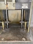
1. The unit stopped 7 months ago due to high vibration and heavy gas leaks from the Gas Control Valve (GCV) valve.
2. The gas valve was serviced and inspected for gas leaks and operation at the site, and it was found to be okay.
3. Realignment was performed.
4. A serviced gas valve was installed.
5. GCV and SRV were calibrated and found to be okay, Vibration sensitivity changed (R core - IO.conf downloaded and rebooted).
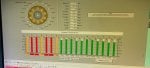
6. GT was started, but the speed did not hold at FSNL.
7. SRV and GCV servo were replaced.
8. The P2 pressure transmitter was calibrated and found to be okay.
9. The hydraulic oil supply is confirmed to be okay.
Despite these efforts, the overspeed issue remains unresolved.
The unit was shut down due to a Gas Valve Leak (GGV leak), and recently, we reinstalled our gas valve in the turbine and realigned it due to high vibration. Upon starting the unit, it was observed that the speed of the Gas Turbine (GT) did not hold at 100% during the Full Speed No Load (FSNL) state; instead, it continuously increased up to 106%. Consequently, we issued an emergency stop for safety concerns.
Unit Specification:
- Unit: Frame 6b (PG6541P)
- Control System: Mark V
- No DLN system installed
Sequence of Events:
1. The unit stopped 7 months ago due to high vibration and heavy gas leaks from the Gas Control Valve (GCV) valve.
2. The gas valve was serviced and inspected for gas leaks and operation at the site, and it was found to be okay.
3. Realignment was performed.
4. A serviced gas valve was installed.
5. GCV and SRV were calibrated and found to be okay, Vibration sensitivity changed (R core - IO.conf downloaded and rebooted).
6. GT was started, but the speed did not hold at FSNL.
7. SRV and GCV servo were replaced.
8. The P2 pressure transmitter was calibrated and found to be okay.
9. The hydraulic oil supply is confirmed to be okay.
Despite these efforts, the overspeed issue remains unresolved.
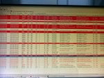
Attachments
-
 253.1 KB Views: 19
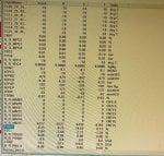
 -
 152.7 KB Views: 17