GE Frame 6B IGV Sticking Issue

Dear All

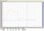
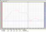
We have GE Frame 6B Gas turbines and we are facing IGV Sticking issues while changing loads. The IGV actuator is stucking at different openings between 42 to 55 degrees intermittently.

Surprisingly, whenever we shutdown turbine and calibrate the IGV system using Mark VI, the calibration becomes successful. Even we have changed the servo valve, but the problem remains the same.

We know that the oil we are using is having a lot of varnish MPC inside it. But my question here is that if there is varnish contributing to this problem, then how it passes the calibration. It always stucks when the turbine is running.

Thanks

Regards
 
gtengineer,

People are always surprised to learn how much force it takes to hold IGVs in a steady-state position, or to move them, when the axial compressor is running at rated speed. It's a good deal of force.

And that force comes from hydraulic pressure and flow, through the servo valve.

This gets said a lot, "It passed calibration." The problems with that statement is: There no real definition of "calibration." And there is a lot of misunderstanding and tribal knowledge.

It could be a problem with the hydraulic actuator seals leaking, especially when there a lot of flow such as when the unit is running, and the required flow to move the IGVs is MUCH less when the unit is not running.

But, that's the two main possibilities: the servo, and the actuator. There is the IGV solenoid, 20TV-1.

By the way, when you change servos, do you perform a servo polarity check? And, if you do--how do you do it?
 
Hi CSA
As always, I found you to help me out. Thanks a lot for your support.

Well I will check about the servo polarity but how it can yield to this problem? As I informed that the IGV is operating but it is sticking in a particular range between 42 to 55 degrees.
 
gtengineer,

How can improper servo current polarity contribute to this problem? When a lot of force is required and one of the servo currents is fighting the other two, that can be a problem.

I would be most suspicious of the hydraulic actuator OR the rack and gears--given the new information. MANY GE-design Frame 6B heavy duty gas turbines have the IGV actuator mounted below the IGVs at the 6 o'clock position, where they get almost ZERO attention from the mechanical--or the Intrumentation & Control--department(s).

BUT, really, the site needs to work on cleaning up the oil.... Because, soon it's going to cause problems with other hydraulically-actuated devices (like fuel control valve(s)!!!).

MOST people (falsely) believe that when they replace a servo-valve they need to "re-calibrate" the device being driven by the servo. NOT TRUE!!!! It is actually more important to perform a servo polarity check of all three servo currents, individually. "Calibration" (contrary to wildly popular--and patently false--beliefs) does NOTHING to the servo or the device (the IGVs, or the fuel control valves). "Calibration" is only for scaling the LVDT feedback--and when a servo is replaced (if that's the only thing that's done) it does NOTHING to change the stroke of the device OR the stroke of the LVDTs. NOTHING. ZILCH. ZERO. NADA. NIENTE. ZIPPO. BUT, it has happened time and time and time again, that from the factory (including from Moog) the servo coil wires have been crossed, causing the servo polarity to be reversed. AND, it's VERY often the case that the servo being removed was not properly tested for servo polarity, so re-connecting the new servo with the exact same color code of leads causes the new servo to have improper servo polarity....

Hope this helps! Please write back to let us know what you find and how you resolve the problem.
 
Dear CSA

When we stroked our IGV system after replacing moog servo valve, we observed spikes in the servo currents on some particular positions. The IGV is also sticking around the same positions. Does it mean that there is some mechanical stickness somewhere in the assembly (which may be due to oil) which is demanding greater servo currents?

Im attaching the IGV feedback vs Servo current trends here.

Regards
 

Attachments

gtengineer,

Yes. That's what the spikes mean. They are pointing to the hydraulic actuator, or the IGV rack and gear mechanism. The cylinder walls of the actuator or the actuator piston stem can be scored, causing mechanic binding.

On one really severe case it was found that three of the four hold-down bolts securing the hydraulic actuator had broken and the one remaining bolt had loosened and the constant actuation had caused the bolt hole to enlarge and the bolt itself to be worn. This caused mechanical binding because the heim joint was not properly aligned. And, of course, the problem was originally blamed on the Mark*.... (Isn't everything the Mark*'s fault?!?!?!!???)

There have also been worn heim joints and bushings which resulted in misalignment and "sticky" operation.
 
gtengineer,

If I'm not mistaken, the graphs you provided are ONLY of IGV LVDT feedback. If that's true, then someone was changing the IGV reference in steps--which is what the graphs show, step changes in position.

When you are using "AutoCalibrate" to manually change the IGV position reference (and that's what I'm presuming how you are stroking (moving) the IGVs), there is usually a graph of servo-valve current, also. With the default graph settings in Trend Recorder the servo current mostly appears to be a straight line, with very small "blips" when the reference changes (larger "blips" when the reference changes by a lot, but the blips are not very large with the default settings). If the IGVs are sticking, what would be seen in the plot of the IGV servo current would be "spikes" of servo current at the point at which as the reference is changing but the LVDT feedback is not the Mark* would be putting out more servo current to try to get the IGV position feedback to change and follow the IGV position feedback. If you plot IGV servo current (usually CAGR), IGV position reference (CSGR) and IGV position feedback (CSGV) when the unit is running and the IGVs are sticking you will see the same thing; when the reference is changing but the feedback is not the servo current will increase until the IGV feedback moves.

(Remember: CSGV is the maximum of the two LVDT feedback signals--so if they aren't both changing at the same time and the same rate, then that could cause problems. But, usually, when one uses "AutoCalibrate" to stroke the IGVs manually both LVDT feedback values are plotted. It's important to know that both LVDT feedback signals are changing at the same time and at the same rate when the IGVs are moving, because if they are not, then that can cause problems--similar to what you are attempting to describe.)

Also, the servo current output from a Mark VI when using "AutoCalibrate" is NOT always smooth; it changes in very small steps, but sometimes when observing the device being stroked it appears the device is "sticking" and its movement does not appear to be smooth. That's the Mark VI, and some versions of VSVO software were worse than others about the smoothness of the servo current outputs. If one changes the resolution of the Trend graph of the device being stroked, it can appear like the device is "jumping" and "sticking" and not moving slowly, but that's quite often just the way the actual VSVO servo current outputs are, which also doesn't really show up well on the Trend graph during "AutoCalibrate." When the unit is running, the outputs are perfectly smooth--they are the result of digital signals, and the outputs change at the rate of 100 Hz (so, as fast as 100 times per second, as the feedback is compared to the reference, the output can change as necessary to try to make the feedback equal to the reference).

Sticking in the range of 42 and 55 degrees is during acceleration, at around 70-80% speed. So, is this problem only occurring during starting before reaching FSNL (rated speed)?

If the oil is REALLY dirty, I would suspect that "new" (or refurbished) servos would still last a few days. Usually, there is a filter on the block/manifold where the servo is connected, and that filter filters the hydraulic oil supply to the servo. When was the last time the filter was changed? (There is almost NEVER a differential pressure gauge or -switch on the "last chance" hydraulic filters (as these filters are affectionately called), only sometimes there is a little "button" on the filter which, when it "pops up" indicates it needs to be replaced.) I have seen last chance filters which have gotten so dirty they don't pass very much oil, and some have even ruptured--which causes dirt and debris which had been captured in the filter to flow downstream, contaminating and ruining the servo-valve(s).

Most electro-hydraulic servo-valves also have what are called "pencil filters" which are very thin, long filters which can be removed and cleaned and re-installed. BUT, the people doing the removal have to know which socket head cap screws to loosen to remove the pencil filter or they risk permanently damaging the servo. AND, they have to clean the area around the servo very well to prevent dirt and debris from getting into the filter cavity while the filter is out and being cleaned, and when the clean filter is being re-installed. (This is something which is very often neglected--cleaning the area around the servo BEFORE replacing it.... Good housekeeping (cleanliness) is VERY important! And, one hands (or gloved hands) need to be clean when working with the new servo, also.)

I'm very keen to know how you are progressing on resolving this issue. But, I wanted to let you know that I don't think the graphs you posted really shown any sticking. I know that the unit was at zero speed when you were recording this information--and you say the sticking only occurs when the unit is running. It's impossible to tell from the graphs you provided if there is any sticking--because it's presumed what is shown on the graph is LVDT feedback (it could be reference!). To see evidence of sticking we would need to see BOTH reference AND position. Sticking would appear as an increasing reference and a lagging, halting feedback. There's only one line in each of the graphs, and we don't know if it's reference or feedback. One can't make ANY determination from the posted graphs.

Please write back to let us know what you are finding!
 
Top