 Facebook
 Google
 GitHub
 Linkedin
Hello Everyone,
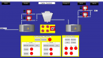
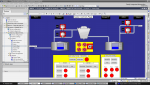
I am new to this forum. I am having an issue with my SCADA design. I am designing a SCADA for a cooling tower system using WINCC professional on TIA portal V18. The main issue is with some of the graphics used during the design stage namely the pipes.
On the design side, all the pipes have been laid out on the operator page. However, when I run the runtime simulation, when viewing the operator page, all the pipes have seemingly shifted or have shortened in length.
I have tried changing the scales, changing settings so the page fits to the screen but it did not solve the issue.
I want to know what could be the issue and how to go about resolving it. Attached is an image of the design on tia portal and the same screen being simulated.
Thank you.
Attachments
-
 108.9 KB Views: 4
 -
 546.6 KB Views: 4


