Facebook
 Google
 GitHub
 Linkedin
We are having serious issue with our GE frame 9E gas turbine, we are having high vibration on #1 bearing, BB1 and BB2 giving high vibration @ 65% speed (1800RPM), The issue started when we did alignment on the machine, so it was concluded that the accessory gear box bearing was bad, it left idle for one year and seven months, earlier this year, the Accessory gear box bearing was bought and fixed and alignment was done, but the vibration is there. We have change the seismic vibration sensor on BB1 and BB2, we have change the card on Mark VI, but the vibration is still there. We have done water wash on the machine. Your opinions is highly needed to help solve the issue.
HIGH VIBRATION ON GE FRAME 9E GAS TURBINE.
- Thread starter EBUWAODUWA
- Start date
Scroll to continue with content
Good day. Did the unbalance occur suddenly? Does it trip? 65% might be close to its critical speed. Does it come down at higher speed? When was the turbine last balanced?
@EBUWAODUWA,
Thank you for opening a specific thread for this issue.
In another thread you wrote:
"... there is no vibration when you stand at the grating, there is no vibration when you put your hand at the bearing casing in #1 bearing."
You also wrote:
"Yes we have a Bentley Navada ..."
So, the problem is being reported by BOTH seismic vibration sensors on the #1 Bearing.
We don't know if the problem is being indicated by the Bently-Nevada sensors on the #1 Bearing, or the #2 Bearing (see below).
The problem started after an 'alignment' was performed on the machine.
The machine was left idle for over one-and-a-half years.
Another alignment of the turbine rotor to accessory load gear coupling was performed.
The problem persisted.
The two seismic vibrations sensors on the #1 Bearing were replaced (with new sensors?). The problem still persists.
There is no physical indication of a vibration issue when someone is standing near the #1 Bearing during STARTing of the machine OR when someone places their hand on the #1 Bearing cap or casing (where the two redundant seismic vibration sensors, BB1 & BB2) are mounted.
There is no report of Diagnostic Alarms on the turbine control system (which is presumed to be a Mark* VI, or possibly a Mark* VIe (???)).
There is no data provided from the Bently-Nevada sensors on the #1 Bearing, or the #2 Bearing.
My best guesses are there is still an alignment issue between the turbine rotor flange (which is very near the #1 Bearing), and/or the seismic vibration sensors are not mounted correctly (securely bolted, with the bolts torqued properly, and/or with the sensor wiring is not properly connected to the interconnecting wiring in the sub-junction box near the #1 Bearing (including the shield drain wires of the sensors). (The latter is unlikely, but still possible.)
Usually, if there is a vibration problem at the #1 Bearing there will also be some vibration transmitted along the axial compressor shaft to the #2 Bearing where it will be registered by the BB3 seismic vibration sensor (there is usually only a single seismic vibration sensor mounted on the #2 Bearing drain piping which is securely connected to the #2 Bearing housing/casing).
It was the case for many years (decades, actually), that for a trip to occur on high vibration of GE-design heavy duty gas turbines equipped with digital Mark* turbine control systems that multiple seismic vibration sensors in one of the groups of seismic vibration sensors (turbine; load gear; generator or driven device) had to indicate alarm and trip vibration levels had been exceeded. The turbine seismic vibration sensors are usually grouped together (BB1 & BB2 on the #1 Bearing, BB3 on the #2 Bearing, and BB4 & BB5 on the #3 Bearing). [I'm presuming the identification of the seismic vibration sensor on the #2 bearing is BB2; but that's an educated guess.] The configuration would require that at least one of the sensors of any of the three turbine (axial compressor and turbine) bearings would have to indicate a high-high vibration (trip) level had been exceeded and at least one of the other seismic vibration sensors was indicating a high vibration level (alarm) had also been exceeded. That's how it USED to be.
From the information provided it does not appear that any of the seismic vibration sensors on either the #2 Bearing OR the #3 bearing are in either alarm or trip levels. AND, there is no report of any indication of excessive vibration on any of the machine bearings being reported by the Bently-Nevada. And it does not appear that there is any noticeable vibration at the Accessory Gear coupling nearest the #1 Bearing.
It would require a review of the seismic vibration block in the application running in the Mark* VI(e) to see what the configuration constants on this machine are. For a time, there were some machines that were installed and commissioned with incorrect seismic vibration configuration constants, and it's NOT easy to just say a particular value should be this or that--there is some binary-to-decimal or decimal to binary conversions of these configuration constants (Control Constants).
There is a document called the 'Control Specification' which should have been provided with the turbine and auxiliary equipment. I don't recall the number of the section that deals with vibration (seismic and possibly proximity) configuration and in one of the sub-sections it should detail the name of the Control Constant which causes the sensors installed on the machine in groups (in the case of a Frame 9E there would only be two groups--turbine and generator), and there will be another Control Constant which configures how the tripping would be accomplished (for example, two or more seismic vibration sensors indicating trip AND one or seismic vibration sensors indicating alarm). I'm NOT saying this is the problem--just that it might be.
I AM SAYING that it would appear there is either still a difficult to perceive vibration issue OR the vibration sensors are not securely mounted to the #1 Bearing cap OR there is some wiring issue (not likely since the high vibration is being reported with two sets of seismic vibration sensors). It could also be that the seismic vibration block in the Mark* VIe application code is not configured correctly--THAT DOESN'T EXPLAIN WHY TWO SETS OF SEISMIC VIBRATION SENSORS ARE STILL REGISTERING HIGH-HIGH VIBRATION ON THE #1 BEARING. And we have no list of any relevant seismic vibration sensor Diagnostic Alarms--so I am presuming there are no issues with the Mark* seismic vibration monitoring components (terminal boards; I/O card(s); etc.).
So, that's all I have for now. Please take the above into consideration.
Thanks for your reply, The approximator did not capture any vibration, The seismic vibration bolted is firmly mounted on the bearing casing, please do you have any document regarding vibration, if you have i will be glad if you can share it with me.
@EBUWAODUWA,
As a controls engineer doing mostly commissioning and maintenance work where a controls engineer was needed I was able to avoid learning too much about, or getting involved, in vibration issues. I have assisted mechanical engineers in gathering vibration data and operating the machine to get data and verification--but I actually avoided becoming any kind of expert in vibration troubleshooting and resolution. Why? Because per my experience watching vibration experts try to explain and educate operators, supervisors and power plant managers about what might be the problem(s) causing their vibration and how to gather data and what would be required to resolve the issue I could clearly see that until the problem was resolved and the report was written the operators, supervisors and power plant managers (and owners) just wanted the problem fixed yesterday and although they wanted all manner of explanations and schedules they really DIDN'T want them--they just wanted the problem fixed yesterday so they wouldn't have to pay for the experts to fix the problem.
In other words, it's pretty much a no-win situation in the data-gathering and problem resolution phases (because sometimes it was necessary to make a couple of balance moves/adjustments--not just one!).
Vibration is really an art with a whole lot of science applied to the art.
I wish I could offer more than the logical thought processes I have offered. It's pretty clear that everyone believes the problem is the turbine control system--and it might be--but if that's the case, why do two separate sets of seismic vibration transducers produce the same result? You haven't (and won't?) provide any information about any Diagnostic Alarms and quite often (I have found) that when I arrive on site and see the Diagnostic Alarms they were clearly trying to tell someone who would even just read the messages that there was a problem with some component of the control system that, if replaced, would solve the problem. Most people consider Diagnostic Alarms to be nuisance alarms--a VERY BIG NUISANCE. And because the false belief that Diagnostic Alarms can't trip the turbine persists everywhere nobody pays attention to them--because the messages tend to be cryptic and they won't trip the turbine. (There are combinations of Diagnostic Alarms that WILL trip a turbine--and the list of combinations would be long and specific to most machines/installations. But, again, there are combinations of Diagnostic Alarms that WILL trip a turbine, and it's usually one Diagnostic Alarm that, when things get so bad it is finally annunciated, will trip the turbine--but there were several related Diagnostic Alarms already warning that things were getting weird that it gets missed in the scheme of things.)
I sense a panic setting in, and that usually leads to quickly discounting potential issues because someone just thinks it can't be "that." Or several "thats."
You say that the vibration occurs at around 65% speed which is just after the typical point that the torque converter (usually a Voith torque converter) is de-pressurized to stop the transfer of torque from the starting/cranking motor to the turbine shaft--and that usually occurs at 60% TNH (turbine shaft speed). I wonder if something could be happening when the torque converter is de-pressurized that is transmitting vibration through the Accessory Coupling to the turbine shaft.?.?.?
But, that's all I can offer you. Even if the Mark* seismic vibration block isn't configured properly if you have two seismic vibration sensors telling you the same thing, and a second set telling you the same thing, and there's no palpable vibration around the #1 bearing and even on the #2 bearing that's NOT the root cause of the problem. Something is shaking the seismic vibration sensors--that's how they work. There are small coils suspended inside and when there is vibration the coils generate a small voltage (millivolts) that the Mark* components can detect and scale into vibration.
Not knowing what Diagnostic Alarms are present before and during the high-high vibration doesn't really give us any information that might point to something amiss with the Mark*. So, at this point, it can't be ruled in OR out as a possible cause. If it's a Mark* VI (and not a Mark* VIe) then the vibration sensors are probably connected to TVIB card which are connected to VVIB cards in the three control processor racks. If it were me, I would probably be ensuring the "black" (sometimes very dark brown) cables that connect the TVIB cards to the VVIB cards are properly inserted and "clipped in" at both ends (on the TVIB(s) and on the VVIBs). [I hope I have then card names correct.]
But I can't think of anything else. BE CAREFUL with the "black" interconnecting cable ends if you accidentally pull one end of a cable out of a stationary receptacle--it's VERY easy to short the male pins of the cable end to the metal portion of the stationary female receptacle when trying to reinsert the cable end into the receptacle and damage a card or a cable. Best to just lightly wiggle the cable ends to be sure they are secure, and if they're not try slipping the "clip" up or down to secure the cable end in the stationary receptacle.
[If you have spare Mark* VI cables in your warehouse best to get one out and have a really good look at how the clips work. And, if you a damaged Mark* VI terminal board with stationary receptables on it it's recommended to make a few tests of clipping the cable ends into the stationary receptacles. It can be very frustrating--and potentially costly--if mistakes are made. It might also be a good idea to check all the "black cables" at both ends soon--when the Mark* Vi is powered down and inputs like the PTs are also de-energized.]
Best of luck. It would be really great to hear what you find as you resolve this problem. I wish I could be of more help.
@EBUWAODUWA,
The turbine is coupled to the starting (cranking) motor through the Accessory Coupling, which connects the turbine shaft to the Accessory Gear Box shaft which is coupled to the torque converter which is coupled to the starting (cranking) motor. The Accessory Gear Box shaft the Accessory Coupling and the torque converter are coupled to is the input shaft to the Accessory Gear Box. I presume that Accessory Gear Box input shaft is the one that had a new bearing installed recently which prompted the alignment procedure.
The torque converter usually has one or two solenoids that control the flow of Lube Oil through the torque converter. 20TU-1 is the solenoid-operated valve that controls the transmission of torque through the torque converter from the starting (cranking) motor to the Accessory Gear Box input shaft and to the turbine shaft through the Accessory Coupling.
Usually, at 60% TNH (turbine shaft speed) the Mark* de-energizes 20TU-1 which causes the torque converter to be de-pressurized which stops the transmission of torque from the starting (cranking) motor to the turbine shaft. The starting (cranking) motor continues to run for a few minutes to cool it down and is then shut down. However, whenever the turbine shaft is turning the output shaft of the torque converter is also turning (there's usually no clutch between the output shaft of the Voith torque converter and the Accessory Gear Box input shaft (and turbine shaft). There is a continual flow of Lube Oil through the torque converter to protect it while it's being spun by the turbine shaft.
You say the high vibration trip happens at around 65% speed, and if I recall correctly you wrote somewhere that it started or tripped around 63% speed. This is very close the speed level and the time that 20TU-1 is deenergized to de-pressure the torque converter.
It may be nothing, but it would seem that the stimulus for the excessive vibration (which you also say doesn't appear to exist) occurs at the time 20TU-1 is de-energized to de-pressure the torque converter--or very shortly after that. I know it's very noisy in the Accessory Compartment when the machine is starting and running but can someone monitor the torque converter and Accessory Gear Box to see if there is some vibration there beginning at about 50-60% speed and increases as the machine accelerates past 60% speed that is being transmitted to the turbine #1 bearing?
You say the machine has Bently-Nevada vibration proximity sensors but that they "capture" any high vibration. Does the machine have a Bently-Nevada vibration monitor to which the proximity sensors and the keyphasor are connected, or are the proximity sensors connected to the Mark* turbine control system? Sometimes there are outputs of a Bently-Nevada vibration monitor that are connected to the Mark* turbine control system for monitoring using the HMI.
[For many years GE actually mounted Bently-Nevada proximity sensors in the machine bearings even if the Customer didn't order or require proximity sensors. This was done to provide a simple way to check vibration and to calculate a balance "shot" if necessary without having to disassemble the machine to install proximity sensors. It was done to provide the proximity readings if a high vibration situation occurred when the machine was under initial warranty after commissioning. So, while the machine may have proximity sensors mounted on the bearings, they may not actually be connected to a vibration monitor or the Mark* turbine control system.]
It may just be a coincidence that the high vibration and tripping is occurring at about the same time or shortly after the torque converter stops transmitting torque to the turbine shaft.
It would be GREAT if you could provide a graph/trend of the BB1 & BB2 vibration levels and the machine speed (TNH) during the start-up. And, if the proximity sensor readings for the turbine #1 bearing are available on the Mark* HMI it would be great if they could be included on the graph trend as well. If you can send a clear photograph of the graph/trend showing the information from about 50% speed to the time the machine trips we could get a clearer picture of when the vibration starts increasing, crosses the alarm level (usually about 0.5 in/sec (13 mm/sec)) and how fast the vibration is increasing before the machine trips.
Based on the information provided this is the best possible solution from my controls perspective (and this IS a controls-related website). Not knowing when the vibration readings start increasing and how fast they increase is a big detractor for being able to offer anything more. 1 in/sec (25.4 mm/sec) vibration means something should be shaking even at approximately 1800 RPM. But you say it's not noticeable to a person or persons in the vicinity of the #1 turbine bearing. And, yet two sets of seismic vibration sensors are both reporting excessively high vibrations. This is quite a mystery and all of us who follow these threads would very much like to know what is discovered and what the solution is!
@EBUWAODUWA,
I have a couple of questions, this will help me to study your case in more detail:
1. What was the vibration and temperature on the bearings before the machine stopped (before alignment)?
2. Did you move the accessory skid during the alignment? If yes, it would be better if you provide the alignment check data before and after the adjustment!
3. What type of auxiliary coupling do you use?
4. How did the vibration and temperature level change on other BB3 bearings, generator bearings?
5. What is the vibration level when the machine is at purge speed (crank speed).
6. Provide specific data on what you call high vibration, exact numbers?
7. If there is data from proxe probs (shaft radial vibration sensors), we also need it!
When it's about to enter self sustaining speed, the high vibration will trip the machine. I don't have access to the trend cause is with the management.@EBUWAODUWA,
The turbine is coupled to the starting (cranking) motor through the Accessory Coupling, which connects the turbine shaft to the Accessory Gear Box shaft which is coupled to the torque converter which is coupled to the starting (cranking) motor. The Accessory Gear Box shaft the Accessory Coupling and the torque converter are coupled to is the input shaft to the Accessory Gear Box. I presume that Accessory Gear Box input shaft is the one that had a new bearing installed recently which prompted the alignment procedure.
The torque converter usually has one or two solenoids that control the flow of Lube Oil through the torque converter. 20TU-1 is the solenoid-operated valve that controls the transmission of torque through the torque converter from the starting (cranking) motor to the Accessory Gear Box input shaft and to the turbine shaft through the Accessory Coupling.
Usually, at 60% TNH (turbine shaft speed) the Mark* de-energizes 20TU-1 which causes the torque converter to be de-pressurized which stops the transmission of torque from the starting (cranking) motor to the turbine shaft. The starting (cranking) motor continues to run for a few minutes to cool it down and is then shut down. However, whenever the turbine shaft is turning the output shaft of the torque converter is also turning (there's usually no clutch between the output shaft of the Voith torque converter and the Accessory Gear Box input shaft (and turbine shaft). There is a continual flow of Lube Oil through the torque converter to protect it while it's being spun by the turbine shaft.
You say the high vibration trip happens at around 65% speed, and if I recall correctly you wrote somewhere that it started or tripped around 63% speed. This is very close the speed level and the time that 20TU-1 is deenergized to de-pressure the torque converter.
It may be nothing, but it would seem that the stimulus for the excessive vibration (which you also say doesn't appear to exist) occurs at the time 20TU-1 is de-energized to de-pressure the torque converter--or very shortly after that. I know it's very noisy in the Accessory Compartment when the machine is starting and running but can someone monitor the torque converter and Accessory Gear Box to see if there is some vibration there beginning at about 50-60% speed and increases as the machine accelerates past 60% speed that is being transmitted to the turbine #1 bearing?
You say the machine has Bently-Nevada vibration proximity sensors but that they "capture" any high vibration. Does the machine have a Bently-Nevada vibration monitor to which the proximity sensors and the keyphasor are connected, or are the proximity sensors connected to the Mark* turbine control system? Sometimes there are outputs of a Bently-Nevada vibration monitor that are connected to the Mark* turbine control system for monitoring using the HMI.
[For many years GE actually mounted Bently-Nevada proximity sensors in the machine bearings even if the Customer didn't order or require proximity sensors. This was done to provide a simple way to check vibration and to calculate a balance "shot" if necessary without having to disassemble the machine to install proximity sensors. It was done to provide the proximity readings if a high vibration situation occurred when the machine was under initial warranty after commissioning. So, while the machine may have proximity sensors mounted on the bearings, they may not actually be connected to a vibration monitor or the Mark* turbine control system.]
It may just be a coincidence that the high vibration and tripping is occurring at about the same time or shortly after the torque converter stops transmitting torque to the turbine shaft.
It would be GREAT if you could provide a graph/trend of the BB1 & BB2 vibration levels and the machine speed (TNH) during the start-up. And, if the proximity sensor readings for the turbine #1 bearing are available on the Mark* HMI it would be great if they could be included on the graph trend as well. If you can send a clear photograph of the graph/trend showing the information from about 50% speed to the time the machine trips we could get a clearer picture of when the vibration starts increasing, crosses the alarm level (usually about 0.5 in/sec (13 mm/sec)) and how fast the vibration is increasing before the machine trips.
Based on the information provided this is the best possible solution from my controls perspective (and this IS a controls-related website). Not knowing when the vibration readings start increasing and how fast they increase is a big detractor for being able to offer anything more. 1 in/sec (25.4 mm/sec) vibration means something should be shaking even at approximately 1800 RPM. But you say it's not noticeable to a person or persons in the vicinity of the #1 turbine bearing. And, yet two sets of seismic vibration sensors are both reporting excessively high vibrations. This is quite a mystery and all of us who follow these threads would very much like to know what is discovered and what the solution is!
@EBUWAODUWA,
Self-sustaining speed is usually around 60% speed--which is when, usually, the torque converter is de-pressurized to stop the transmission of torque from the starting/cranking motor to the machine's shaft through the Accessory Coupling.
But that's NOT enough information--as evidenced by the questions asked by @Aibol.
I sincerely doubt that we can help you if you can't provide more information. GE-design heavy duty gas turbines are intricate machines and vibration on the #1 bearing can be caused by many things. I will repost what I wrote earlier on in the thread:
The problem started after an 'alignment' was performed on the machine.
The machine was left idle for over one-and-a-half years.
Another alignment of the turbine rotor to accessory load gear coupling was performed.
The problem persisted.
The two seismic vibrations sensors on the #1 Bearing were replaced (with new sensors?). The problem still persists.
There is no physical indication of a vibration issue when someone is standing near the #1 Bearing during STARTing of the machine OR when someone places their hand on the #1 Bearing cap or casing (where the two redundant seismic vibration sensors, BB1 & BB2) are mounted.
There is no report of Diagnostic Alarms on the turbine control system (which is presumed to be a Mark* VI, or possibly a Mark* VIe (???)).
There is no data provided from the Bently-Nevada sensors on the #1 Bearing, or the #2 Bearing.
There simply is not enough information to be able to help you with this problem. I understand that the mechanical department believes there is no vibration and that the bearing replacement and realignment were done satisfactorily. Yet, based on the information provided, the seismic (velocity) vibration sensors on the #1 bearing--TWO SETS of seismic (velocity) vibration sensors--are BOTH indicating nearly the same vibration levels. Yet, we have no Bently -Nevada vibration information/data from the #1 bearing.
I would like to hear how this problem is resolved--but it seems you are going to need to have someone familiar with the machines and vibration monitoring, and probably alignment procedures, to travel to site to help with resolving the problem.
I wish you the best of luck, sir.
Good morning sir, compliment of the day, Thanks for your reply, mi tried sending the video of the vibration here but the file is large. i don't know if you can send me your Email so that i can forward it to you. before the machine trip on high vibration, first BB3 is reading 6.5 after a while BB1 and BB2 flash yellow, after some seconds it flash red and trip. BB3 is the one that rises first. YOU CAN WRITE ME [email protected]@EBUWAODUWA, Self-sustaining speed is usually around 60% speed--which is when, usually, the torque converter is de-pressurized to stop the transmission of torque from the starting/cranking motor to the machine's shaft through the Accessory Coupling. But that's NOT enough information--as evidenced by the questions asked by @Aibol. I sincerely doubt that we can help you if you can't provide more information. GE-design heavy duty gas turbines are intricate machines and vibration on the #1 bearing can be caused by many things. I will repost what I wrote earlier on in the thread: The problem started after an 'alignment' was performed on the machine. The machine was left idle for over one-and-a-half years. Another alignment of the turbine rotor to accessory load gear coupling was performed. The problem persisted. The two seismic vibrations sensors on the #1 Bearing were replaced (with new sensors?). The problem still persists. There is no physical indication of a vibration issue when someone is standing near the #1 Bearing during STARTing of the machine OR when someone places their hand on the #1 Bearing cap or casing (where the two redundant seismic vibration sensors, BB1 & BB2) are mounted. There is no report of Diagnostic Alarms on the turbine control system (which is presumed to be a Mark* VI, or possibly a Mark* VIe (???)). There is no data provided from the Bently-Nevada sensors on the #1 Bearing, or the #2 Bearing. There simply is not enough information to be able to help you with this problem. I understand that the mechanical department believes there is no vibration and that the bearing replacement and realignment were done satisfactorily. Yet, based on the information provided, the seismic (velocity) vibration sensors on the #1 bearing--TWO SETS of seismic (velocity) vibration sensors--are BOTH indicating nearly the same vibration levels. Yet, we have no Bently -Nevada vibration information/data from the #1 bearing. I would like to hear how this problem is resolved--but it seems you are going to need to have someone familiar with the machines and vibration monitoring, and probably alignment procedures, to travel to site to help with resolving the problem. I wish you the best of luck, sir.
@EBUWAODUWA,
Sometimes videos taken with a smartphone can be very large (in MB or even GB). I don't know what the maximum file upload size is on Control.com but if you have a video taken with a smartphone I strongly suggest you copy the video file from your smartphone to a computer and then use a program to convert the file to a .jpeg (.jpg) or .png file format and see if that reduces the file size.
But, this is the problem with NOT providing actionable data early in the thread--because now you are saying that the #2 Brg.--which has the vibration sensor identified as BB3 mounted on the L.O. drain pipe housing of the #2 Brg. drain--increases in magnitude before the sensors on the #1 bearing increase to the alarm and trip level. As was written before, it's very typical that the vibration protection logic running in the Mark* turbine control requires multiple sensors in a group of sensors (in your case, the turbine sensors--all three bearings--are one group) to be indicating excessive vibration (alarm AND trip levels) before the machine will trip (because vibration is almost always transmitted along the shaft to more than one bearing of a three-bearing machine like a GE-design Frame 9E heavy duty gas turbine).
I don't understand the engineering units being used for the vibration monitoring and protection--are you saying the #2 Brg. Vibration (as measured by BB3) is 0.65 in/sec or 6.5 mm/sec during the start-up?. Usually the seismic (velocity) vibration sensor engineering units are expressed in either in/sec or mm/sec, and the alarm level for GE-design heavy duty gas turbines is 0.5 in/sec (approximately 12.5 mm/sec) and the trip level is 1.0 in/sec (approximately 25.4 mm/sec).
Again, I'm NOT any kind of vibration expert. AND, the conditions of this thread are changing with time. A vibration level of 0.65 in/sec on the #2 bearing can usually be felt when standing on the grating near the turbine compartment--at lower speeds it's not quite so noticeable sometimes BUT one's toes should be tingling a little bit with a vibration as high as 0.65 in/sec. AND, it's been reported that there is no noticeable vibration around on on the #1 Brg. area during the start-up when the machine speed is approximately 60-65%. And NOW it's being reported that the #2 Brg. is experiencing vibration above the alarm level prior to the #1 Brg. alarming and tripping.
THERE IS SOME KIND OF MECHANICAL ISSUE WITH THE MACHINE--MOST LIKELY THE ACCESSORY COUPLING AND/OR THE ACCESSORY COUPLING ALIGNMENT, OR THE BEARING THAT WAS REPLACED ON THE ACCESSORY GEAR ASSEMBLY.
These--mechanical--questions have been asked before, well, one of them anyway...
1) What is the temperature of the oil in the Lube Oil tank when the machine is being STARTed? If it's below approximately 70-80 deg F then it's colder than it should be and that can cause vibration problems during STARTing.
2) How long is the machine ON COOLDOWN (ratchet; or slowroll) prior to initiating a START? YES--a GE-design heavy duty gas turbine can be STARTed from zero speed---but only if the rotor is warm (lowest wheelspace temperature more than about 150 deg F) OR it has been less than 24 hours since the machine was taken off COOLDOWN after running at load and being shutdown (or tripped) and was ON COOLDOWN for the requisite time (usually 24 hours; sometimes the minimum COOLDOWN period is based on the highest wheelspace temperature).
3) If the machine uses a ratchet mechanism for COOLDOWN has someone visually confirmed the rotor turns about 45 deg approximately every 3 minutes, continuously while ON COOLDOWN?
I have ONE suggestion, though I'm not certain it will help--but it won't hurt either. Ready the machine for STARTing, being sure the L.O. Tank Temperature is greater than 80 deg F and the L.O. Bearing Header temperature is at least 80 deg F, also, AND put the machine ON COOLDOWN for at least 4 hours while monitoring L.O. Bearing Header temperature to be sure that it doesn't go below 80 deg F. When 4 hours of COOLDOWN operation have been completed, select FIRE from the Master Control selector on the GE Mark* HMI. Confirm the HMI display is showing a READY TO START indication, and initiate a START of the machine.
The machine will go through a normal purge sequence and then start coasting down in speed, and when the speed gets just below approximately 10% TNH the rotor will start accelerating slowly again after 10-30 seconds and when the speed passes through 10% TNH the machine will go into a firing sequence--energizing the ignitors (spark plugs) and admitting fuel into the combustors to establish flame. Once flame has been detected the fuel flow will reduce slightly and REMAIN at the "warm-up" FSR (Fuel Stroke Reference) value. The machine will probably begin accelerating faster BUT the fuel flow-rate into the combustors will only change very slightly. Again--continue to monitor the L.O. Bearing Header temperature--it should NOT drop below approximately 80 deg F! If it does, you will need to find a way to TEMPORARILY stop the flow of cooling water to L.O. coolers to prevent the L.O. temperature from dropping below 80 deg F.
I suggest also watching the #1 Brg. and #2 Brg. seismic vibration values--recording them every few seconds if possible (take photos using a smartphone and attach them to your next response). This data will be helpful.
Let the machine run in this condition--be patient!!!--and after 20 minutes or so, time to let the turbine rotor begin warming and the bearings begin warming up, select AUTO from the Master Control Select area of the Mark* HMI. At this point the fuel flow will start increasing and the machine speed will also start increasing more quickly--as normal after a minute or so.
As the machine speed approaches 60% TNH, start a video recording of the Vibration display of the Mark* HMI--the entire page, not just the bargraphs. The machine may trip shortly after the torque converter is de-pressurized--and if it does then this warming-up sequence did NOTHING to reduce whatever the stimulus is that's causing the excessive vibration--BUT it DID NOT hurt anything either. If the machine trips please continue to record the Vibration display of the Mark* HMI for another 10 seconds or so. Again, it may be necessary to convert the video file format to something smaller (.jpg/.jpeg or .png) to be able to attach it to a response. You may need to attach the files to multiple responses to this thread to get them all added to the thread.
If the machine manages to get to FSNL (Full Speed-No Load) then I would also suggest waiting for 15-30 minutes to let the machine continue warming up for the suggested period before synchronizing the machine. OR, after the 15-30 warm-up period the machine can be STOPped by selecting STOP and letting the machine go through a normal fired shutdown and automatically go ON COOLDOWN and remain ON COOLDOWN for the normal minimum time if it's not going to be started again in the next 24 hours or so. (When a machine is ON COOLDOWN, it can be STARTed by just selecting AUTO and clicking on START and confirming the command. It is NOT necessary to wait for the machine to complete it's COOLDOWN period to take it OFF COOLDOWN--all that's required is to make sure the machine Master Control is set to AUTO and then click on START and confirm the command (if or when a READY TO START indication is given).
So, that's all I have for now. I can answer most controls-related questions and offer suggestions--as I have--but, again, I AM NOT a controls expert by any measure. I can say in this case based on the information provided (which changes periodically...) that it certainly does not appear the problem is controls-related. I can't tell you exactly what else to investigate--though I have offered some ideas, which I know are time-consuming and expensive. You may (hopefully) find that the warming-up procedure suggested may help, and it may not. And if it doesn't, then--in my experience and opinion based on the information provided--the issue of this thread is mechanical and not controls.
Best of luck--and please write back to let us know what kind of progress you are making and how the issue is being resolved. MANY people read these threads now--and in the future--and your feedback about the issue and how it was resolved may be very helpful to someone at some time in the future (maybe even now!).
I FIRMLY believe--though I have been wrong in the past, and I may be wrong about this, and I will be wrong in the future--THERE IS A MECHANICAL PROBLEM CAUSING THE EXCESSIVE VIBRATION DURING STARTING. I don't care what the mechanical department says--or whomever performed the Accessory Coupling alignment--or what Plant Management says. THE MARK* SEEMS TO BE WORKING PROPERLY AND SENSING AND REPORTING EXCESSIVE SEISMIC VIBRATION (based on the information provided). And I also firmly believe the issue with the machine at your site IS NOT a controls-related issue--based on the information provided. And while occasionally a person knowledgeable in GE heavy duty gas turbine vibration problems stops by and posts to threads here at Control.com, it doesn't any such individual is currently reading this thread or able to provide any useful suggestions or they probably would have already.
So, that's all I have for now. If you will perform the warming-up sequence as outlined above and attach the data to the post (again--it may require multiple responses and you or someone familiar with video file formats may have to convert the video file to a smaller format) we can at least have some actionable data to review. I do not think it's going to change my opinion about whether or not it's a controls-related issue or not, but someone may be following this thread and see something useful they can comment on.
I'm also NOT SAYING it's definitely a problem with the Accessory Coupling/alignment--it's just that, based on the information provided, that seems to be the thing that was last worked on and that's always a good place to start troubleshooting. It could be an imbalance on the axial compressor rotor--but we don't know what the vibrations of the #1- and #2 Brgs. looks like before reaching approximately 60-65% TNH and the machine trips. It could be a problem with the oil flow-rate to the bearings. A photo of the machine bearing temperatures and L.O. drain temperatures when the machine is approaching 50% (NOT a typo!) TNG might also be helpful--but AGAIN: THESE ARE ALL MECHANICAL ISSUES.
If the machine has a separate Bently-Nevada vibration monitor it would also be very helpful if someone could be recording (video) that monitor to see if there's something there that might spark a comment. If it doesn't have a Bently-Nevada vibration monitor, does the Mark* HMI have a Bently-Nevada vibration display--and can it be recorded as the machine approaches 60% speed and for a short time afterwards, also? (And attached to this thread.)
When troubleshooting a problem like this it's often helpful for several people to sit down and come up with a list of the possible issues which could cause the problem. Then, the team needs to work together to prioritize the possibilities from most likely to least likely--while considering all of the available data. And then start investigating each possibility from most likely to least likely to either prove one of them IS the problem or IS NOT the problem. Try to have conditions during the data-gathering as consistent as possible (L.O. temperature, for example, in this case; 4 hours or so of warm-up on COOLDOWN before initiating a START; etc.). And, finally, have some take some notes during each troubleshooting/investigation phase of what was done, how it was done, and what the results were (NOT just that the problem didn't go away--but sometimes certain things do change).
You have been provided a pretty comprehensive list of possibilities and, BASED ON THE INFORMATION PROVIDED it DOES NOT appear the problem is controls-related. You have replaced the seismic (velocity) vibration sensors and the replacements indicate the same excessive vibrations. The Mark* doesn't look at anything other than seismic vibration inputs to determine if the machine should be tripped or not--not the speed of the machine, not the oil temperature--nothing else. Period. Full stop. It's a relatively simple monitoring and protection scheme. So, I suggest if it is important to get this machine up and producing electric power that someone seriously consider checking the various mechanical issues which have been suggested. Performing the warm-up sequence--as outlined--WILL NOT hurt, and it might help.
What do you see or feel the high vib ?
@barita2619,
This problem was originally posted to another unrelated thread. A moderator created a new thread for this problem, and the original poster created still another thread (this one).
See reply #2 above.
And continue reading and you will see the information dribbles in and even changes. It’s virtually impossible to have two sets of vibration sensors indicate more than 1.0 in/sec on the same bearing and “the” Mark* VI vibration card(s) to have been changed, also, and for no one to feel the sensations of more than 1.0 in/sec. We have asked for data but have received only anecdotal data (verbal data) with no evidence.
If you have any ideas or suggestions please share them with us.
@EBUWAODUWA,
Sometimes videos taken with a smartphone can be very large (in MB or even GB). I don't know what the maximum file upload size is on Control.com but if you have a video taken with a smartphone I strongly suggest you copy the video file from your smartphone to a computer and then use a program to convert the file to a .jpeg (.jpg) or .png file format and see if that reduces the file size.
But, this is the problem with NOT providing actionable data early in the thread--because now you are saying that the #2 Brg.--which has the vibration sensor identified as BB3 mounted on the L.O. drain pipe housing of the #2 Brg. drain--increases in magnitude before the sensors on the #1 bearing increase to the alarm and trip level. As was written before, it's very typical that the vibration protection logic running in the Mark* turbine control requires multiple sensors in a group of sensors (in your case, the turbine sensors--all three bearings--are one group) to be indicating excessive vibration (alarm AND trip levels) before the machine will trip (because vibration is almost always transmitted along the shaft to more than one bearing of a three-bearing machine like a GE-design Frame 9E heavy duty gas turbine).
I don't understand the engineering units being used for the vibration monitoring and protection--are you saying the #2 Brg. Vibration (as measured by BB3) is 6.5 in/sec during the start-up?. Usually the seismic (velocity) vibration sensor engineering units are expressed in either in/sec or mm/sec, and the alarm level for GE-design heavy duty gas turbines is 0.5 in/sec (approximately 12.5 mm/sec) and the trip level is 1.0 in/sec (approximately 25.4 mm/sec).
Again, I'm NOT any kind of vibration expert. AND, the conditions of this thread are changing with time. A vibration level of 6.5 in/sec on the #2 bearing can usually be felt when standing on the grating near the turbine compartment--at lower speeds it's not quite so noticeable sometimes BUT one's toes should be tingling a little bit with a vibration as high as 6.5 in/sec. AND, it's been reported that there is no noticeable vibration around on on the #1 Brg. area during the start-up when the machine speed is approximately 60-65%. And NOW it's being reported that the #2 Brg. is experiencing vibration above the alarm level prior to the #1 Brg. alarming and tripping.
THERE IS SOME KIND OF MECHANICAL ISSUE WITH THE MACHINE--MOST LIKELY THE ACCESSORY COUPLING AND/OR THE ACCESSORY COUPLING ALIGNMENT, OR THE BEARING THAT WAS REPLACED ON THE ACCESSORY GEAR ASSEMBLY.
These--mechanical--questions have been asked before, well, one of them anyway...
1) What is the temperature of the oil in the Lube Oil tank when the machine is being STARTed? If it's below approximately 70-80 deg F then it's colder than it should be and that can cause vibration problems during STARTing.
2) How long is the machine ON COOLDOWN (ratchet; or slowroll) prior to initiating a START? YES--a GE-design heavy duty gas turbine can be STARTed from zero speed---but only if the rotor is warm (lowest wheelspace temperature more than about 150 deg F) OR it has been less than 24 hours since the machine was taken off COOLDOWN after running at load and being shutdown (or tripped) and was ON COOLDOWN for the requisite time (usually 24 hours; sometimes the minimum COOLDOWN period is based on the highest wheelspace temperature).
3) If the machine uses a ratchet mechanism for COOLDOWN has someone visually confirmed the rotor turns about 45 deg approximately every 3 minutes, continuously while ON COOLDOWN?
I have ONE suggestion, though I'm not certain it will help--but it won't hurt either. Ready the machine for STARTing, being sure the L.O. Tank Temperature is greater than 80 deg F and the L.O. Bearing Header temperature is at least 80 deg F, also, AND put the machine ON COOLDOWN for at least 4 hours while monitoring L.O. Bearing Header temperature to be sure that it doesn't go below 80 deg F. When 4 hours of COOLDOWN operation have been completed, select FIRE from the Master Control selector on the GE Mark* HMI. Confirm the HMI display is showing a READY TO START indication, and initiate a START of the machine.
The machine will go through a normal purge sequence and then start coasting down in speed, and when the speed gets just below approximately 10% TNH the rotor will start accelerating slowly again after 10-30 seconds and when the speed passes through 10% TNH the machine will go into a firing sequence--energizing the ignitors (spark plugs) and admitting fuel into the combustors to establish flame. Once flame has been detected the fuel flow will reduce slightly and REMAIN at the "warm-up" FSR (Fuel Stroke Reference) value. The machine will probably begin accelerating faster BUT the fuel flow-rate into the combustors will only change very slightly. Again--continue to monitor the L.O. Bearing Header temperature--it should NOT drop below approximately 80 deg F! If it does, you will need to find a way to TEMPORARILY stop the flow of cooling water to L.O. coolers to prevent the L.O. temperature from dropping below 80 deg F.
I suggest also watching the #1 Brg. and #2 Brg. seismic vibration values--recording them every few seconds if possible (take photos using a smartphone and attach them to your next response). This data will be helpful.
Let the machine run in this condition--be patient!!!--and after 20 minutes or so, time to let the turbine rotor begin warming and the bearings begin warming up, select AUTO from the Master Control Select area of the Mark* HMI. At this point the fuel flow will start increasing and the machine speed will also start increasing more quickly--as normal after a minute or so.
As the machine speed approaches 60% TNH, start a video recording of the Vibration display of the Mark* HMI--the entire page, not just the bargraphs. The machine may trip shortly after the torque converter is de-pressurized--and if it does then this warming-up sequence did NOTHING to reduce whatever the stimulus is that's causing the excessive vibration--BUT it DID NOT hurt anything either. If the machine trips please continue to record the Vibration display of the Mark* HMI for another 10 seconds or so. Again, it may be necessary to convert the video file format to something smaller (.jpg/.jpeg or .png) to be able to attach it to a response. You may need to attach the files to multiple responses to this thread to get them all added to the thread.
If the machine manages to get to FSNL (Full Speed-No Load) then I would also suggest waiting for 15-30 minutes to let the machine continue warming up for the suggested period before synchronizing the machine. OR, after the 15-30 warm-up period the machine can be STOPped by selecting STOP and letting the machine go through a normal fired shutdown and automatically go ON COOLDOWN and remain ON COOLDOWN for the normal minimum time if it's not going to be started again in the next 24 hours or so. (When a machine is ON COOLDOWN, it can be STARTed by just selecting AUTO and clicking on START and confirming the command. It is NOT necessary to wait for the machine to complete it's COOLDOWN period to take it OFF COOLDOWN--all that's required is to make sure the machine Master Control is set to AUTO and then click on START and confirm the command (if or when a READY TO START indication is given).
So, that's all I have for now. I can answer most controls-related questions and offer suggestions--as I have--but, again, I AM NOT a controls expert by any measure. I can say in this case based on the information provided (which changes periodically...) that it certainly does not appear the problem is controls-related. I can't tell you exactly what else to investigate--though I have offered some ideas, which I know are time-consuming and expensive. You may (hopefully) find that the warming-up procedure suggested may help, and it may not. And if it doesn't, then--in my experience and opinion based on the information provided--the issue of this thread is mechanical and not controls.
Best of luck--and please write back to let us know what kind of progress you are making and how the issue is being resolved. MANY people read these threads now--and in the future--and your feedback about the issue and how it was resolved may be very helpful to someone at some time in the future (maybe even now!).
I FIRMLY believe--though I have been wrong in the past, and I may be wrong about this, and I will be wrong in the future--THERE IS A MECHANICAL PROBLEM CAUSING THE EXCESSIVE VIBRATION DURING STARTING. I don't care what the mechanical department says--or whomever performed the Accessory Coupling alignment--or what Plant Management says. THE MARK* SEEMS TO BE WORKING PROPERLY AND SENSING AND REPORTING EXCESSIVE SEISMIC VIBRATION (based on the information provided). And I also firmly believe the issue with the machine at your site IS NOT a controls-related issue--based on the information provided. And while occasionally a person knowledgeable in GE heavy duty gas turbine vibration problems stops by and posts to threads here at Control.com, it doesn't any such individual is currently reading this thread or able to provide any useful suggestions or they probably would have already.
So, that's all I have for now. If you will perform the warming-up sequence as outlined above and attach the data to the post (again--it may require multiple responses and you or someone familiar with video file formats may have to convert the video file to a smaller format) we can at least have some actionable data to review. I do not think it's going to change my opinion about whether or not it's a controls-related issue or not, but someone may be following this thread and see something useful they can comment on.
I'm also NOT SAYING it's definitely a problem with the Accessory Coupling/alignment--it's just that, based on the information provided, that seems to be the thing that was last worked on and that's always a good place to start troubleshooting. It could be an imbalance on the axial compressor rotor--but we don't know what the vibrations of the #1- and #2 Brgs. looks like before reaching approximately 60-65% TNH and the machine trips. It could be a problem with the oil flow-rate to the bearings. A photo of the machine bearing temperatures and L.O. drain temperatures when the machine is approaching 50% (NOT a typo!) TNG might also be helpful--but AGAIN: THESE ARE ALL MECHANICAL ISSUES.
If the machine has a separate Bently-Nevada vibration monitor it would also be very helpful if someone could be recording (video) that monitor to see if there's something there that might spark a comment. If it doesn't have a Bently-Nevada vibration monitor, does the Mark* HMI have a Bently-Nevada vibration display--and can it be recorded as the machine approaches 60% speed and for a short time afterwards, also? (And attached to this thread.)
When troubleshooting a problem like this it's often helpful for several people to sit down and come up with a list of the possible issues which could cause the problem. Then, the team needs to work together to prioritize the possibilities from most likely to least likely--while considering all of the available data. And then start investigating each possibility from most likely to least likely to either prove one of them IS the problem or IS NOT the problem. Try to have conditions during the data-gathering as consistent as possible (L.O. temperature, for example, in this case; 4 hours or so of warm-up on COOLDOWN before initiating a START; etc.). And, finally, have some take some notes during each troubleshooting/investigation phase of what was done, how it was done, and what the results were (NOT just that the problem didn't go away--but sometimes certain things do change).
You have been provided a pretty comprehensive list of possibilities and, BASED ON THE INFORMATION PROVIDED it DOES NOT appear the problem is controls-related. You have replaced the seismic (velocity) vibration sensors and the replacements indicate the same excessive vibrations. The Mark* doesn't look at anything other than seismic vibration inputs to determine if the machine should be tripped or not--not the speed of the machine, not the oil temperature--nothing else. Period. Full stop. It's a relatively simple monitoring and protection scheme. So, I suggest if it is important to get this machine up and producing electric power that someone seriously consider checking the various mechanical issues which have been suggested. Performing the warm-up sequence--as outlined--WILL NOT hurt, and it might help.
i can't send the video cause the file is mp4. I have compressing the mp4 video file but it's working.@barita2619,
This problem was originally posted to another unrelated thread. A moderator created a new thread for this problem, and the original poster created still another thread (this one).
See reply #2 above.
And continue reading and you will see the information dribbles in and even changes. It’s virtually impossible to have two sets of vibration sensors indicate more than 1.0 in/sec on the same bearing and “the” Mark* VI vibration card(s) to have been changed, also, and for no one to feel the sensations of more than 1.0 in/sec. We have asked for data but have received only anecdotal data (verbal data) with no evidence.
If you have any ideas or suggestions please share them with us.
@EBUWAODUWA,
Use your preferred World Wide Web search engine with this search term:
How to convert mp4 to jpeg
Or:
How to convert mp4 to png
There are some very good free video converters available for download. I STRONGLY RECOMMEND you use a desktop computer to perform the conversion.
Question #1) Are you still convinced that when standing in the Accessory Compartment near the #1 Brg. or on the grating outside the Turbine Compartment near the #2 Brg. that no vibrations can be felt? 0.5 or 1.0 in/sec is a lot of movement.
Question #2) Did you replace the TVIB terminal board?
Question #3) Is the Mark* VI a SIMPLEX or TMR control system? Because if it is a TMR control system there should be a VVIB card in each of the control processor racks (<R>, <S>, & <T>) and while it’s possible that all three VVIB cards could be failing it’s extremely unlikely AND there would be Diagnostic Alarms to indicate some kind of issue with the seismic vibration monitoring & protection system.
@EBUWAODUWA,
My thoughts keep going back to the reason the machine was not operated for over a year--something to do with the Accessory Coupling and a failed Accessory Gear Box bearing. I believe you said the machine had undergone a maintenance outage, during which an alignment of the Accessory Coupling to the machine (or to the Accessory Gear Box--it was never quite clear--PLEASE CONFIRM). It seems that after the maintenance outage was completed (including the Accessory Coupling alignment!) there was some vibration during starting. It seems that subsequently a bearing of the Accessory Gear Box failed and was eventually replaced--prompting another Accessory Coupling alignment to be performed. PLEASE CONFIRM THE SEQUENCE EVENTS.
And, the second alignment of the Accessory Coupling was performed and it did not resolve the problem.
You say the vibration increases first on the #2 Brg. of the turbine and then on the #1 Brg. It the vibration gets very strong on the #1 Brg. just before or right after approximately 60% TNH and increases to trip level (probably 1.0 in/sec) around 65% speed.
As has been written, it's customary for the Mark* to de-pressurize the torque converter (by de-energizing solenoid 20TU-1) at 60% TNH. The starting motor continues to run for a few minutes after the torque converter is de-pressurized to cool the starting motor after the start and acceleration of the machine to 60% TNH. All the time during the START and up to 60% TNH torque is being transmitted through the torque converter from the starting motor to the machine shaft (and through the Accessory Gear Box and the Accessory Coupling). I suspect that's why the vibration is not so high when torque is being transmitted (at least not high enough to trip the machine) because torque is being transmitted through the Accessory Coupling.
But, once the torque converter is de-pressurized and the machine has to continue accelerating by increasing the fuel flow-rate if the Accessory Coupling is misaligned slightly the vibration might actually increase to/through the #1 Brg.--and that's what the seismic vibration sensors are detecting. This is all speculation, but it's a possibility, if even a slim one. It seems the last thing that was done was to align the Accessory Coupling (we don't know if it was to the turbine or to the Accessory Gear Box...!). And, it also seems that it was the first thing that was done a very long time ago after the maintenance outage.
The last thought I have is that the off-line water wash was not performed correctly--specifically the rinse. LOTS of people use the recommended amount of detergent--or even slightly more detergent than recommended by the detergent manufacturer and then they become impatient performing the rinse and don't get all of the detergent out of the axial compressor area and the combustion section. The longest and heaviest part of the turbine shaft (I'm not including the generator rotor!) is the axial compressor; it's long and it's heavy. If there is detergent residue on the axial compressor shaft from improper rinsing, possible excessive detergent use, and improper CRANKing and drying procedure then that could be the cause of the imbalance. (I've only seen this happen once, but it is a real thing.)
REMEMBER: Detergent manufacturers are in the business of selling detergent. The more detergent used during each wash the more detergent they sell! So, their recommendation is for the most possible detergent concentration to sell as much detergent as possible.
Rinsing after off-line water washing is important--very important. Rinsing requires a LOT of water, and a lot of time--both of which can be challenging to find after completing the "wash cycle." And increasing the amount of detergent above that recommended by the detergent manufacturer is going to require MORE rinsing--which most people don't have the required patience to do. The recommendation from GE is to rinse until the false start drains show clear water with no suds/bubbles. And, again, even using the manufacturer's recommended amount of detergent requires a LOT of water and patience.
My personal recommendation is to initially use about half of what the detergent manufacturer recommends and after rinsing is complete inspect the axial compressor for cleanliness. If it's not as clean as desired, increase the amount of detergent on the next off-line water wash procedure. And, again, inspect the axial compressor after rinsing to determine the degree of cleanliness and how to proceed with future off-line water wash procedures (specifically, the amount of detergent being used).
But, both of these possibilities--remote as they are--are still mechanical in nature, and not related to controls. We aren't there alongside you, so we don't know what you know, we don't know the exact details and sequence of events, and we don't know exactly what you are experiencing, AND we don't have any data from a failed START to analyze. We can only know what you are telling us. And, still, (and I'm probably going to regret repeating this...): Based on the information provided the problem appears to be mechanical, not controls. The mechanical department should be doing more (than we know they've done) to prove it's NOT mechanical. Based on the information provided the controls do not seem to be the cause of the indicated high vibration--the Mark* VI is simply reporting and acting on the information it receives from the seismic vibration sensors. At this point it's the control system against the mechanical department.
Now, we also don't have any chronological list of alarms--Process Alarms OR Diagnostic Alarms. So, it's possible something is amiss with the controls--BUT WE DON'T HAVE ANY EVIDENCE TO SUGGEST THE MARK* VI IS THE CAUSE OF THE PROBLEM. If the Mark* VI is having "internal" problems it is almost always indicated by one or more Diagnostic Alarms. If there are no related Diagnostic Alarms (including Voting Mismatch Diagnostic Alarms!) then it's highly unlikely the problem is with the hardware of the Mark* VI. Now the machine was not operated for many months--and we ALSO don't know if the Mark* VI was powered and running during that period.... So, you see, there's still a lot we don't know about the Mark* VI.
Modern digital control systems (and the Mark* IV IS modern--it's just not the latest version of Mark*) don't "drift"--meaning the setpoints and parameters used to control and protect the equipment being operated don't change with time. In the old days of discreet components (resistors and capacitors and potentiometers) setpoints and parameters did drift over time, including with changes in temperature. But, modern control systems don't suffer from that problem; component quality is much improved and most setpoints and parameters are stored on some kind of memory (memory chips) and don't change unless someone changes them. So, again, as many wires and LEDs as the Mark* VI has DOES NOT mean that it is impossible to understand or that it can't be trusted to monitor, control and protect the multi-million USD equipment it's connected to. AND, it has internal error-checking and reporting--Diagnostic Alarms. They really do mean something, those nuisance Diagnostic Alarms.
Anyway, data is king. But, no matter--it's probably going to lead to the same outcome: A mechanical problem.
Troubleshooting is often a process of elimination. Really difficult problems can often be the result of more than one stimuli or set of problems--so making a list of possibilities and prioritizing them (even if that includes economic/cost considerations) and starting at the top of the prioritized list and working logically and methodically down the list, eliminating possible causes along the way, is often the only way the root cause(s) are going to be determined. The mechanical department is wasting time. The lack of Diagnostic Alarm lists and actual operating data is wasting time. The two can be done simultaneously.
This is the picture i can send at this time@EBUWAODUWA,
My thoughts keep going back to the reason the machine was not operated for over a year--something to do with the Accessory Coupling and a failed Accessory Gear Box bearing. I believe you said the machine had undergone a maintenance outage, during which an alignment of the Accessory Coupling to the machine (or to the Accessory Gear Box--it was never quite clear--PLEASE CONFIRM). It seems that after the maintenance outage was completed (including the Accessory Coupling alignment!) there was some vibration during starting. It seems that subsequently a bearing of the Accessory Gear Box failed and was eventually replaced--prompting another Accessory Coupling alignment to be performed. PLEASE CONFIRM THE SEQUENCE EVENTS.
And, the second alignment of the Accessory Coupling was performed and it did not resolve the problem.
You say the vibration increases first on the #2 Brg. of the turbine and then on the #1 Brg. It the vibration gets very strong on the #1 Brg. just before or right after approximately 60% TNH and increases to trip level (probably 1.0 in/sec) around 65% speed.
As has been written, it's customary for the Mark* to de-pressurize the torque converter (by de-energizing solenoid 20TU-1) at 60% TNH. The starting motor continues to run for a few minutes after the torque converter is de-pressurized to cool the starting motor after the start and acceleration of the machine to 60% TNH. All the time during the START and up to 60% TNH torque is being transmitted through the torque converter from the starting motor to the machine shaft (and through the Accessory Gear Box and the Accessory Coupling). I suspect that's why the vibration is not so high when torque is being transmitted (at least not high enough to trip the machine) because torque is being transmitted through the Accessory Coupling.
But, once the torque converter is de-pressurized and the machine has to continue accelerating by increasing the fuel flow-rate if the Accessory Coupling is misaligned slightly the vibration might actually increase to/through the #1 Brg.--and that's what the seismic vibration sensors are detecting. This is all speculation, but it's a possibility, if even a slim one. It seems the last thing that was done was to align the Accessory Coupling (we don't know if it was to the turbine or to the Accessory Gear Box...!). And, it also seems that it was the first thing that was done a very long time ago after the maintenance outage.
The last thought I have is that the off-line water wash was not performed correctly--specifically the rinse. LOTS of people use the recommended amount of detergent--or even slightly more detergent than recommended by the detergent manufacturer and then they become impatient performing the rinse and don't get all of the detergent out of the axial compressor area and the combustion section. The longest and heaviest part of the turbine shaft (I'm not including the generator rotor!) is the axial compressor; it's long and it's heavy. If there is detergent residue on the axial compressor shaft from improper rinsing, possible excessive detergent use, and improper CRANKing and drying procedure then that could be the cause of the imbalance. (I've only seen this happen once, but it is a real thing.)
REMEMBER: Detergent manufacturers are in the business of selling detergent. The more detergent used during each wash the more detergent they sell! So, their recommendation is for the most possible detergent concentration to sell as much detergent as possible.
Rinsing after off-line water washing is important--very important. Rinsing requires a LOT of water, and a lot of time--both of which can be challenging to find after completing the "wash cycle." And increasing the amount of detergent above that recommended by the detergent manufacturer is going to require MORE rinsing--which most people don't have the required patience to do. The recommendation from GE is to rinse until the false start drains show clear water with no suds/bubbles. And, again, even using the manufacturer's recommended amount of detergent requires a LOT of water and patience.
My personal recommendation is to initially use about half of what the detergent manufacturer recommends and after rinsing is complete inspect the axial compressor for cleanliness. If it's not as clean as desired, increase the amount of detergent on the next off-line water wash procedure. And, again, inspect the axial compressor after rinsing to determine the degree of cleanliness and how to proceed with future off-line water wash procedures (specifically, the amount of detergent being used).
But, both of these possibilities--remote as they are--are still mechanical in nature, and not related to controls. We aren't there alongside you, so we don't know what you know, we don't know the exact details and sequence of events, and we don't know exactly what you are experiencing, AND we don't have any data from a failed START to analyze. We can only know what you are telling us. And, still, (and I'm probably going to regret repeating this...): Based on the information provided the problem appears to be mechanical, not controls. The mechanical department should be doing more (than we know they've done) to prove it's NOT mechanical. Based on the information provided the controls do not seem to be the cause of the indicated high vibration--the Mark* VI is simply reporting and acting on the information it receives from the seismic vibration sensors. At this point it's the control system against the mechanical department.
Now, we also don't have any chronological list of alarms--Process Alarms OR Diagnostic Alarms. So, it's possible something is amiss with the controls--BUT WE DON'T HAVE ANY EVIDENCE TO SUGGEST THE MARK* VI IS THE CAUSE OF THE PROBLEM. If the Mark* VI is having "internal" problems it is almost always indicated by one or more Diagnostic Alarms. If there are no related Diagnostic Alarms (including Voting Mismatch Diagnostic Alarms!) then it's highly unlikely the problem is with the hardware of the Mark* VI. Now the machine was not operated for many months--and we ALSO don't know if the Mark* VI was powered and running during that period.... So, you see, there's still a lot we don't know about the Mark* VI.
Modern digital control systems (and the Mark* IV IS modern--it's just not the latest version of Mark*) don't "drift"--meaning the setpoints and parameters used to control and protect the equipment being operated don't change with time. In the old days of discreet components (resistors and capacitors and potentiometers) setpoints and parameters did drift over time, including with changes in temperature. But, modern control systems don't suffer from that problem; component quality is much improved and most setpoints and parameters are stored on some kind of memory (memory chips) and don't change unless someone changes them. So, again, as many wires and LEDs as the Mark* VI has DOES NOT mean that it is impossible to understand or that it can't be trusted to monitor, control and protect the multi-million USD equipment it's connected to. AND, it has internal error-checking and reporting--Diagnostic Alarms. They really do mean something, those nuisance Diagnostic Alarms.
Anyway, data is king. But, no matter--it's probably going to lead to the same outcome: A mechanical problem.
Troubleshooting is often a process of elimination. Really difficult problems can often be the result of more than one stimuli or set of problems--so making a list of possibilities and prioritizing them (even if that includes economic/cost considerations) and starting at the top of the prioritized list and working logically and methodically down the list, eliminating possible causes along the way, is often the only way the root cause(s) are going to be determined. The mechanical department is wasting time. The lack of Diagnostic Alarm lists and actual operating data is wasting time. The two can be done simultaneously.
Attachments
-
 90.6 KB Views: 18
This is the picture i can send at this time
Attachments
-
 652.1 KB Views: 11
This is when BB3 is going up before Bb1 and BB2 follow up.
Attachments
-
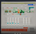 617.4 KB Views: 13