I want to ask, hopefully someone can help

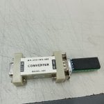
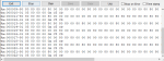
I'm learning how to connect Modbus to a computer using a USB to RS486 converter and I keep getting a checksum error message.
Wiring:

A+ to A+
B- to B-
GND to GND

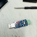
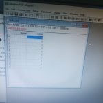
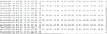
I adjusted the setup according to the manual and have tried all slave IDs from 1 to 200
but the checksum error persists.

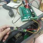
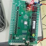
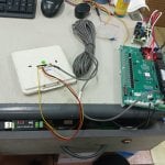
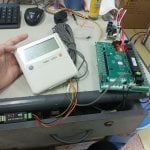
In the photo, it can be seen that I connected the modbus from the master to the conferter, but before that I connected the modbus from the MCB to the conferter and it still gave a checksum error.
 

Attachments

Welcome to the forum!

Here are some basic Modbus troubleshooting suggestions.

Modbus RTU can only have one master connected to the bus. If you are trying to connect your computer using a USB to RS-485 adapter to an existing Modbus RTU network (consisting of the white display and green control board shown in your photos), this will not work.

Try swapping the A and B wires. Not all manufacturers use the same polarity for A and B signal labeling.

So that we can help you further, please tell us the manufacturer and models of the equipment involved, or better yet, attach users manuals and communication documentation for the devices here. Please also tell us what software you're using when communicating using your USB to RS-485 adapter.
I have the manual, and you can see it.
I use Modbus Poll software

So, should I connect the Modbus converter directly to the MCB? Not to the wallpad? (white screen in the attached photo)
thanks
 

Attachments

According to the manual you attached, the wallpad should be connected to the TTL1 connector on the MCB, which you appear to already have. But your USB to RS-485 adapter should be connected to the green terminal block terminals (BMS connection port) on the MCB, not to the wallpad (the manual you attached makes no mention of the wallpad supporting RS-485 or Modbus).

I would try connecting the USB to RS-485 adapter to the A1, B1, and GND terminals on the MCB (note, as previously mentioned, you may need to try both polarities for the A and B connections).
I've previously tried connecting to a modbus terminal block, but the result was the same checksum error. I've also tried swapping cables A and B, and tried different slave IDs, but to no avail.
 
It might be an issue with your USB to RS-485 converter.

Do you have anything else connected to the RS-485 wiring, such as termination resistors? Perhaps the USB to RS-485 has a pre-installed termination resistor (I've seen this on some cheap converters). What is the specific converter you're using?

Do you get a checksum error even without anything connected to the converter?

Do you have a different USB to RS-485 converter (preferably from a different manufacturer) that you can try?
I've tried connecting this converter to another Modbus device, but it worked without error.

I've also tried replacing the converter (as shown in the picture), but the checksum error persists.

There are no other components connected to the converter.

The checksum error only appears when the device is connected.
 

Attachments

I think I found your converted and this page confirms it does have a built in 120 ohm termination resistor, which very well could be the cause of your issue.
https://www.waveshare.com/usb-to-rs485.htm

You could desolder that 120 ohm resistor(or otherwise disconnect it, such as by snipping/destroying it with a cutters) or apply idle biasing (pull-up and pull-down) resistors to the A and B lines (for example, one 680 ohm resistor from A+ to 5V and another 680 ohm resistor from B- to GND.
after i took it apart, i didn't see any resistor inside
 

Attachments

The termination resistor is on the underside of the board, as shown on the Waveshare page I linked in my last reply. It is the small black rectangle near the green terminal block with "121" printed on it in white.
 
Another suggestion. When using Modbus Poll, you can view the Modbus packets exchanged between Modbus Poll and the Modbus slave device by clicking on the "Display" menu and selecting "Communication...". This will open the Communication Traffic window and show the data sent and received by Modbus Poll.

Seeing the communication traffic may be useful so that we can determine if any of the received bytes actually look valid and perhaps just the checksum (CRC technically) is wrong, or if all of the received bytes are garbled. Please post a screenshot of Modbus Poll's Communication Traffic window when this issue is occurring.
Thank you for your reply. Here, the RXD and TXD converters are flashing alternately, and the status only displays a checksum error, as shown in the image.
 

Attachments

What does Modbus Poll's Communication Traffic window show? You can open this by clicking on the "Display" in the top menu and clicking "Communication...".

Does the RXD LED on the converter turn off completely, or does it always stay on?
 
And what difference, if any, is there in the RXD LED and the Communication Traffic window if you swap your A and B connections on one end?
I don't think there is any difference in the display and the RXD LED

I also tried replacing the mainboard PCB, afraid there was a fault on the mainboard, but it was the same.
 

Attachments

If swapping the polarity of the A and B lines results in the same behavior, that seems to imply that the termination resistor is essentially shorting the bus, resulting in an invalid idle voltage of less than 200mV between the A and B signals. Under this invalid state, the converter sees this as constantly receiving (mostly 0's).

Have you tried my suggestion of removing the termination resistor or applying pull-up and pull-down idle biasing to the A and B lines?
I will try to remove the resistor, please wait for my latest update, and thank you for your suggestions.
 
Do you have an ohm meter (multimeter)?

It's possible the MCB also has a termination resistor enabled or permanently installed. You could confirm this by powering the device off, disconnecting the wires from the A and B terminals, and measuring the resistance between A and B. If it measures near 120 ohms, then it has a termination resistor, so you would also need to disable or remove this.

If possible, it may be better to connect biasing resistors. You don't have to use exactly 680 ohms, you could probably use anything from between approximately 500 ohms to 1k ohms. They should just both be the same.
 
There appears to be a jumper on the MCB next to the green terminal block. I believe the manual calls it S3 in the wiring diagram, but does not seem to make any mention of its purpose. Is there any labeling near this jumper? It's possible this jumper enables or disables termination on the MCB.
 
Top