MarkV: PTBA, L14HR and Ratcheting

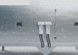
Two frame V gas turbines, one having Mark V while other having Mark VIe control system, are installed at our site. Both turbines were installed with Mark Mark V, but one of the Mark V was upgraded to Mark Vie in 2019. Mark V was initially configured with I but in 2008 I was upgraded to HMI (computer based and with cimplicity). Each gas turbine has its own HMIs, one in the GT compartment and the other HMI in the control room. The fuel used for the gas turbines is Natural Gas.

We are facing and issue with the turbine with Mark V. We faced the same problem four years ago and was shared in this forum as well. The link to that problem is given below

https://control.com/forums/threads/markv-l14hr-and-racheting-issue.47166/

I am mentioning the problem and the steps we have taken so far in this post.

We are using three magnetic pickups. Same pickups are used for R, S, T and P core. The speed pickups cables come to the R, S and T core from area, and are jumpered to P core from RST. Hard-wire jumpers are not installed at P cores’ PTBA-3 to -4, and -7 to -8, and -11 and -12 i.e. only -1 to 2, -5 to -6 and -9 to -10 are connected with three magnetic pickups.

Turbine was shutdown and was not under any maintenance. It was showing ready to start status. Turbine cooldown sequence was off. Turbine was at rest speed and L14HR was 1.

From last couple of days, L14HR is toggling its value after some random hours i.e. it changes to 0 for few seconds and then again came back to 1. It should be noted that the turbine was at rest speed. Due to the transition of L14HR, “PROTECTIVE MODULE ACCELERATION TRIP- HP” alarm appears and the ratcheting starts for 24 hours. However, as L14HR is toggling randomly and before 24 hours the timer (T62CD) for L62CD gets reset, therefore, we are unable to stop the ratcheting unless we force L62CD.

Following steps are taken to troubleshoot the problem

  • Upon going through the alarms, events and SOEs history, we came to know that diagnostic alarm “Voter mismatch, R L12H_ACC” appears sometimes and “Voter mismatch, S L12H_ACC” appears other times, at regular but random intervals.
  • Resistance of all the speed pickups was checked and was found 210, 209 and 197 ohms. Grounding of these wires was checked and they were not showing any resistance with ground. No AC or DC voltages were found on the speed pickups wires.
  • On HMI, pre-vote value of speed for R, S and T was zero, however, when we checked the speed values on diagnostic counters screen for TCE1, we found that TCE1 for R was showing 60 Hz and 1.18% speed. The TCE1 or S and T were showing 0 Hz and 0% speed. Does pre-vote screen shows values of TNH (voted and pre-voted) and TCE1 on diagnostic counter shows TNH_OS?
  • We connected the wires on all the cores and the readings on pre-vote screen and TCE1 screens were 0. When the “Voter mismatch, R L12H_ACC” alarm appears the value on both screen changes for few moments (up to 50%) and then returns to 0.
  • Again the wires of all three pickups from PTBA card were removed, but pickups were still connected with the RST. As soon as the wires were removed diagnostic counters TCE1 screen for R started to show 60 Hz and 1.18% TNH, whereas, pre-vote screen was showing 0%. The voltage and Hz were checked on the terminals of PTBA. PTBA -1 to -2 was showing 60Hz and 75mVac. PTBA -3 to -4, -5 to -6 and -7 to -8 were showing 60 Hz and 8 mVac, but it should be noted that diagnostic counter TCE1 screen for S was showng 0 Hz and 0% TNH. PTBA -9 to -10 and -11 to -12 were showing 0 Hz and 0 mVac and its respective TCE1 was showing 0 as well.
  • Ribbon cable JU connects speed signals from PTBA card to TCEB card. The ribbon cables JKX, JKY and JKZ connects the speed signals from TCEB to TCE1 of X, Y and Z respectively. We removed the ribbon cable JKX and the value on the diagnostic counters for TCE1 of R core changed to 0 Hz and 0% TNH.
  • The JKX was connected back and the TCE1 again started to show the above mentioned values. This time the ribbon JU was removed from the PTBA card. The values changed to 0 on diagnostic counters. 60 Hz and mVac were still present on the terminals of PTBA in this condition.
  • All the ribbon cables from PTBA were removed from one by one, but the mVac and Hz were still present on the PTBA terminals. RST and XYZ were powered down from power distribution core. The voltages and Hz could still be measured on the PTBA terminals. There were only BUS PT voltages coming on the PTBA this time.
What can be the reason of these voltages on the PTBA terminals? We will disconnect the BUS PT voltages and will measure again and will give feedback. Bus PT is sending 120 Vac 60Hz. The frequency on PTBA terminals is same as our generated power frequency. Is there any chance that PTBA is faulty?

What else can be checked? I am unable to share the alarms as USB was not allowed at the site this time.
 
Can you share or provide more details on the sentence that you wrote :
"However, as L14HR is toggling randomly and before 24 hours the timer (T62CD) for L62CD gets reset, therefore, we are unable to stop the ratcheting unless we force L62CD. "

I got a CSP file for a frame6B showing some rungs with L62CD /L1Z/L14HR... can you share those rungs so we can compare ...

Otherwise i cannot support remotely...

As you mentionned that L14HR is toggling randomly ...how did you come to the conclusion that BUS PT VOLTAGE can be the soucre of this problem..
Did this unit worked /operated smoothly i mean without such issue before??

With more datas that you can share the best we can support you!

James
 
ControlsGuy25

Can you share or provide more details on the sentence that you wrote :
"However, as L14HR is toggling randomly and before 24 hours the timer (T62CD) for L62CD gets reset, therefore, we are unable to stop the ratcheting unless we force L62CD. "

L14TV1 is used for speed logic sensing. L14HR is "1" when the TNH is less than 0.06%, and is "0" when TNH is more than 0.31%. Once L14HR is "0", it will not become "1" unless the TNH drops below 0.06%. As the system is TMR, when two cores sense the speed beyond 0.31% the L14HR goes to "0". From the statement above, I meant that two cores were randomly reading the speed resulting in the transition of L14HR between "0" and "1".

When L62CD is "0", the ratcheting can not be started. L62CD is output of a timer, driven by L14HR. When L14HR is "0", L62CD goes to "0", but, when L14HR becomes "1" , L62CD changes to "1" after a time period of 24 hours (24 hours delay). It the turbine was running, and is shutdown this time delay will not let ratcheting stop for 24 hours AND this is desired as well. However, in our case turbine was not running and the toggling or L14HR was not letting the L62CD set to "1".


As you mentionned that L14HR is toggling randomly ...how did you come to the conclusion that BUS PT VOLTAGE can be the soucre of this problem..
Did this unit worked /operated smoothly i mean without such issue before??

PTBA was isolated from TCEB and TCEAs by removing all the ribbon cables. There wasn't any power on the PTBA except BUS PT Voltage. When speed pickups were disconnected the 60Hz frequency was found on the terminals of PTBA. As an isolated terminal board should not read any frequency, hence, we thought that this might be due to BUS PT voltage.

Yes the unit was operating smoothly before.

We further proceeded as
  • The BUS PT voltages were removed, and the frequency was gone from all the PTBA speed pickup terminals.
  • The PTBA card was replaced and BUS voltages were reconnected. I don't know it is normal or not, but, when BUS PT voltages are connected, we are getting 60Hz on PTBA terminals -1 to -2 only. The isn't any frequency on other pickup terminals.
  • Although after replacing the PTBA frequency disappeared from all terminals except -1 to -2, the issue remained as such.
  • We checked the DC voltages w.r.t to ground on the wires of probes going to area and found 24VDC. As this was abnormal, we changed the cables from JB to control panel. The problem has not re-occurred after replacing the loop wires till now.
Esoteric Stone,

Thank you for these clarifications..

I was aware about L14HR and L62CD how they are combined together to get the L1ZMaster control relay ( I got one CSP file for a frame 6B with me here)

Anyway thank you for getting the scenario in place.

Well something is definitely not correct at your site regarding the Toggling of L14HR.. Do you have any frozen screen on HMI ,,I am sayin that since i witnessed a malfunction of some input signal due to HMI screens frozen becasue of a faulty AC/DC filter...

I will review closer this thread and come back with comments to add.

Regards,
James
 
PTBA-1 &-2, and -5 & -6 and -9 & -10 are for the three HP shaft overspeed pickups (TNH_OS). They are used by the TCEA cards in Loc's. 1, 3 and 5 (TCE1 in the I/O Configurator for <Q> (<R>, <S> & <T>)). There were some issues in the Mark* V product life that resulted in spurious and intermittent speed signal problems in <P> that were ultimately resolved by using jumpers between PTBA -3 & -4, and -7 & -8 and -11 & 12--which are the LP shaft speed pick-up inputs. Just a single, short wire jumper between each pair of terminals did the trick. So, three short jumpers between each pair of the LP shaft speed pick-up inputs is all that was required. Easy, peasy.

YES, the GEN and BUS PT inputs are connected to the <P> core on the PTBA. That means the speed signal wiring and the PT input wiring probably lay in the cable trough under the PTBA terminal board for some distance. (The 60 Hz signal you see indicates there is probably some induced signals from the PT inputs on the HP speed input wiring.) If the jumpers for the HP speed inputs to <P> from <R>, <S> & <T> are NOT twisted, shielded pairs--they should be. And, one end of the shield drain wire (ONLY one end of the shield drain wire) should be grounded/earthed in the Mark* V panel (there are ground/earth bars on the I/O terminal board locations for most of the control- and protective processors). The twisted, shielded pair jumpers for the HP speed inputs should also be properly made--meaning the unshielded conductors should not be more than 5-8 cm in length and BOTH ends. (GE did have a bad habit of using unshielded, twisted pair wiring for the speed pick-up jumper wires between <Q> and <P> for a while, they stopped it, but then went back to it (probably a cost-savings and a labor-savings--which meant more cost-savings--and GE was ALL ABOUT cost-savings back then, giving monetary awards for stepping over a dollar to pick up a dime.)

The PT wiring is actually considered "high level" signal wiring--as such, it should be routed in the panel properly (which the design of the Mark* V made difficult but not impossible ....). And, some installers were known to use a LOT of zip-ties to hold wires together that shouldn't have been held together, and most don't really understand instrumentation wiring (and barely understand residential wiring, which is usually the experience they had--if they had any at all, and there were usually not well-supervised (not that the supervisors understood instrumentation wiring, or the commissioning personnel).

So, make sure the wiring is as it should be. Adding the wire jumpers on the LP speed pick-up inputs hurts nothing, and may even help the problem. This should resolve your problem. It might take tracing the routing of the speed pick-up jumpers and the PT inputs to fully sort the problem and possibly re-routing the PT wiring if necessary, and if you went to the other panels odds are that they are not all wired the same--even the factory wiring may be different, but most likely the field wiring would be different.
 
ControsGuy25,
There aren't any frozen screens on HMI.

WTF,
Your explanation was very good. Thanks for sharing.

1. Terminals PTBA -3 & -4, and -7 & -8 and -11 & 12 are neither used nor shorted on our site. We will do that on next available opportunity.

2. The jumpers from Q to P core are twisted pair cables with shield and the shield is only connected on one end.

The problem on our site is resolved by replacing the speed pickup cables from JB1 to control panel. We changed these because we found 24Vdc on these cables when measured w.r.t. ground.

I have a question if you can answer that. When speed pickup cables are disconnected from the PTBA (all cables from terminal -1 to -12), why we are getting 60Hz with 75 mVac on PTBA -1 to -2 ONLY? On diagnostic counters TCE1 screen of R is also showing 60Hz and 1.18% speed. PTBA -3 to -12 are showing 0 Hz and diagnostic counters TCE1 screen for D and T is showing 0 as well. What is the probable cause of this behaviour?
 
Top