Modbus RTU "interruptions" and uneven voltages

Hello to everyone, new member here... :)

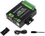
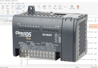
I've built a CNC machine where I control the VFD using modbus from UCCNC software, using Waveshare Industrial Isolated converter (USB to RS485).

Hardware:
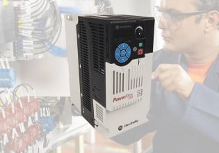
VFD to motor connected with shielded cable for spindles, length 4m, grounded at both sides
RS485 converter connected with shielded cable to the VFD, terminated with 120ohm resistors on both sides, connection length about 30cm (putting it further doesnt change anything). Grounded at GND terminal at VFD.

Following problem:
1) I get random "pauses" in transmission signal - so for few seconds I see constant data flow, then it has hiccup for like 1-2seconds and goes further again for few seconds and it repeats. Depending on speed and modbus delay it changes a bit (those pauses are more or less frequent) but I cannot really get it to run "constantly", this sometimes delays also my controlling signals to the VFD obviously. Those pauses are more frequent when VFD runs, but not dramatically worse.
2) I decided to measure the RS485 signal with an oscilloscope (in1 +, in2 -, ground connected to ground terminal) and here is what I got. Uneven voltage levels is problem nr 1. The second thing is, that as soon as the VFD starts those "stable" signals jump all over the screen suddenly and it is hard to get stable reading. I also see reflection of the signal after around 2-3ms if I measure correctly.

I will be grateful for ideas - where could I look for answers,what could be the problem, why the voltage levels on A+ and B- line are different. Picture is in the STOP mode (spindle not running).
 

Attachments

The uneven voltage levels and sporadic communication could be a bus loading issue. What happens if you remove the 120 resistors and make sure any termination settings on the converter and VFD are disabled? Note that with such a short cable, termination is not necessary for this application.

The uneven voltage levels and stability of the signals when the VFD starts may indicate incorrect grounding of either or both the RS-485 reference and the cable shielding. Note that the Waveshare's "PE" terminal is poorly labeled. It is not "Protective Earth", but rather is "Signal Ground". The VFD should have a COM terminal or GND terminal associated with its RS-485 terminals that the WaveShare's PE terminal should be connected to. As far as shielding, your shield drain wire should be terminated at only one end of the cable to an earth ground. Although this is typically done at the front/head end controller on the network, this may be easier for you to do at the VFD end.

What is the vendor and model of the VFD?

It appears that your oscilloscope image is of just one device's transmission. What does the other device's transmission look like? Does it also have a reduced level on it's RS-485 - signal?

Another thing to keep in mind, it appears you're oscilloscope is a stand-alone unit that requires wall power. By connecting this oscilloscope to your RS-485 network, you are now introducing another ground reference from the scope itself, which could cause more issues to the RS-485 communication or could produce false readings in the oscilloscope. The best scopes to use for RS-485 networks is a battery powered oscilloscope or a USB powered oscilloscope powered from a laptop on battery power.
 
The uneven voltage levels and sporadic communication could be a bus loading issue. What happens if you remove the 120 resistors and make sure any termination settings on the converter and VFD are disabled?
in my VFD and Waveshare adapter there is no option to turn it off. But removing them makes the signal few percent higher (I can see on the oscilloscope that it jumps by maybe 100-200mV.

Note that with such a short cable, termination is not necessary for this application.
ok

The uneven voltage levels and stability of the signals when the VFD starts may indicate incorrect grounding of either or both the RS-485 reference and the cable shielding. Note that the Waveshare's "PE" terminal is poorly labeled. It is not "Protective Earth", but rather is "Signal Ground". The VFD should have a COM terminal or GND terminal associated with its RS-485 terminals that the WaveShare's PE terminal should be connected to.
In the picture you can see my RS485 adapter. my VFD has GND near RS485 and other digital inputs/outputs - this is where I connected Ground terminal from adapter.

As far as shielding, your shield drain wire should be terminated at only one end of the cable to an earth ground. Although this is typically done at the front/head end controller on the network, this may be easier for you to do at the VFD end.
sorry for my ignorance - which shield do you mean exactly? Shield of RS485 cable?

What is the vendor and model of the VFD?
SAKO SKI780

It appears that your oscilloscope image is of just one device's transmission. What does the other device's transmission look like? Does it also have a reduced level on it's RS-485 - signal?
I am sorry, I forgot to describe the picture. Yellow is A+, Blue is B- (lower level) and Red is Math function from oscilloscope CH1-CH2.

Another thing to keep in mind, it appears you're oscilloscope is a stand-alone unit that requires wall power. By connecting this oscilloscope to your RS-485 network, you are now introducing another ground reference from the scope itself, which could cause more issues to the RS-485 communication or could produce false readings in the oscilloscope. The best scopes to use for RS-485 networks is a battery powered oscilloscope or a USB powered oscilloscope powered from a laptop on battery power.
I do not have such, but I have separating 230V trafo / can it help in this case?

Thank you very much for taking time to answer.
 

Attachments

in my VFD and Waveshare adapter there is no option to turn it off. But removing them makes the signal few percent higher (I can see on the oscilloscope that it jumps by maybe 100-200mV.
What you are observing indicates that termination is still connected. According to the Waveshare wiki (https://www.waveshare.com/wiki/USB_TO_RS232/485/422/TTL#Matching_Resistor), the converter's termination resistors are controller by jumpers inside the unit and are on by default. Take the unit apart and move the jumpers to turn off termination. After you modify these jumpers, the RS-485 signals should both swing the full voltage range.

sorry for my ignorance - which shield do you mean exactly? Shield of RS485 cable?
Yes, the shield on the RS-485 cable.

I am sorry, I forgot to describe the picture. Yellow is A+, Blue is B- (lower level) and Red is Math function from oscilloscope CH1-CH2.
I was able to figure this out from your oscilloscope image. But what I was saying is that the capture looks like it is just a single packet from one of the devices (either a single request from the Waveshare or a single response from the drive). Can you take a capture that includes both the request from the Waveshare and the response from the drive?
 
Thank you for the video. I'm assuming Ch1 (yellow) is RS-485 - and Ch2 (blue) is RS-485 +. I'm also assuming the transmissions from the VFD have the larger voltage swing and greater delay, compared to the transmissions from the Waveshare adapter (although there is a chance this assumption backwards).

My guess is that the Waveshare adapter's RS-485 circuitry has been partially damaged, specifically the RS-485 - line. As you can see from the below image (captured from your video), for the Waveshare's request (circled in green), the RS-485 - line does not change when the RS-485 + line does.
1695997187512.png

While this partial damage does not cause complete disruption to the RS-485 communication and still allows some successful communication, it significantly reduces the robustness of the communication. This is likely why, when you run the VFD, the additional noise generated by the VFD that couples into the signal lines sometimes prevents the VFD from successfully receiving the request, and so the VFD does not respond, resulting in a long pause (a timeout).

Furthermore, both the RS-485 signals' idle voltages appear to be around 3.3V. While this is normal for the RS-485 + signal, the RS-485 - signal should be about 0V. There seems to be a short circuit between a 3.3V source and the RS-485 - line, perhaps in the Waveshare adapter due to damage to its RS-485 circuitry.

If you disconnect the RS-485 wires from the VFD, do the Waveshare converter's + and - signals still appear asymmetrical? What happens if you connect a 120 ohm resistor across the the Waveshare's + and - terminals and measure its + and - signals (this is applying a load to the converter's RS-485 circuitry). If the signals appear asymmetric when performing this test, this seems to confirm the Waveshare adapter is partially damaged.

With no wires connected to the VFD, what constant voltage level (idle voltage) does your oscilloscope show when measuring the VFD's RS-485 + and - terminals? Ideally, you should see the RS-485 + terminal at a high voltage level (near 3.3V or 5V) and the RS-485 - terminal at a low voltage level (near 0V).

Do you have a different USB to RS-485 converter that you can test with the VFD and use the oscilloscope to analyze the signals and compare? This would confirm if it is in fact an issue with the Waveshare adapter.
 
Again some video tests follow up:

tests without VFD connected are in the second part of the video. Seems like without VFD, the voltages on both lines are identical... so maybe the china VFD is simply bad?
 
Thank you for the follow up video.

It does certainly seem like the VFD's RS-485 circuitry is damaged, as it appears the adapter's voltage levels swing the full range and the same phenomenon of reduced voltage on the RS-485 - line occurs with your spare USB to RS-485 adapter. Perhaps you can work with the VFD manufacturer to replace the VFD's control board.

You did note that communications seems to work better, without interruptions, with the spare converter, despite the signal being degraded in the same manner as the original isolated converter. I suspect this is due to the slight differences in voltages, loading and the receive sensitivity of the spare converter that just happen to make it work better.

Your observations here highlight the robustness of the RS-485 design, in that even with only one signal working properly, communications is still successful. It makes one wonder how many installations there are in the field with poor signal quality or partially damaged equipment that are just working well enough. In any case, I applaud your effort and thoroughness to investigate the communication issues you are having.
 
Perhaps you can work with the VFD manufacturer to replace the VFD's control board.
I am afraid that in this case (china product) it might be hard to do (we are talking about the cheapest stuff on the market). Even the external panel is not working here properly and documentation for Modbus was like REALLY bad translation and quality, so it cost me a lot of time and experiment to make it work.

So most probably, I will just try to save for a branded VFD like Hitachi model or something from european manufacturer. And till this time I will just live with it...

Thank you for taking the time to analyze my problem. There are not many Modbus specialists on the CNC forum where I got the control board from, so I had to figure a lot by myself and just accidentally found this forum :).

I will do a follow up if I happen to find the branded VFD somewhere cheaply and we will see if this works better.

Thanks!
 
Top