Power Plant Load and Frequency fluctuation - 3 Steam Turbines - Woodward 505E - Power Plant Connected to the Public Grid.

Hello dear fellows;

I need your help please,

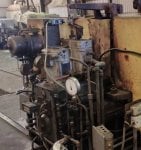
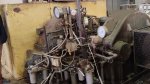
A power generation plant consists of 3 steam turbines each ( 4.8 MW - 6600 V - 50 Hz ) these turbines feed a network of an oil facility which demand currently 7 MW and when all equipment it demands 11 MW but mainly demand 7 MW.

This power plant is also connected to a public grid which is 220 KV - almost 5000 MW - 50 Hz by two main breakers to the busbar.

So, now we have 4 power sources ( 3 Breakers from 3 Steam Turbines and 1 breaker from national grid as the other breaker is usually disconnected; this busbar is 6600 V - 50 Hz - 7 MW )

The 3 steam turbines are controlled by Woodward 505E, each unit is totally separated the other, No common HMI, No DCS, No Woodward 505E HMI workstation, and No power management system.

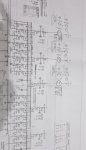
In the Configuration documents the following is noted :
Speed Control Droop Settings:
Droop % 5
Use KW Droop Yes
Gen Load Units No

The Problem :
During and after the commissioning of Woodward505E control System ( before units were controlled by pneumatic classic control system ) we suffer form the following:

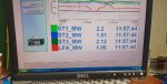
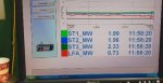
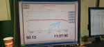
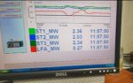
Whenever we have frequency and load fluctuation at the national grid trend Breaker A1 ( Electric Shedding sys. is used and has graphs ) then immediately we suffer bad fluctuation in the output power ( Active power trend output ) of the 3 steam turbines by almost 1 MW and each Generator start producing power and decreasing power and for 1 or 2 seconds the reading of the National Grid MW become Minus (- ....)
until the operator start Rising the speed of one or two steam turbine at the same time so the output load of the 3 Generators and the feeder come to stability.

This happens multiple time a day...

And when we shut down 1 unit the network and loads are relatively stable and when we put the Two National Girds (220 KV) Feeders on the main busbar (6600) with the other units then the frequency and loads are relatively stable.

Please find attached Trends,

Please help me with your technical opinions and experience in analyzing this problem.

Kind Regards.
 

Attachments

Are your governors capable of isoch control. It appears the governors are fighting each other when isolated from the grid.
Thank you Mr. Curious_One for immediate response,
They are hydraulic governors, and this generators competing is happening even when they synchronized on the same grid with the National Grid,
but when the 6600 main busbar frequency dips, this fluctuation in active power,
please see attached photo for the Governor
 

Attachments

KevinCanada,

What does the control system integrator who provided the Woodward 505E's say about the problem??? What are they doing to try to help with the resolution?

What has been done to try to help resolve the problem?

And, most importantly, what were the results of the efforts to try to resolve the problem (other than there has been little or no improvement)?

It would be REALLY helpful to see a one-line diagram of the plant and the utility ties (the 2 high-voltage ties, and the 6KV tie).

I wonder if the three steam turbine-generators feed a common step-up transformer, or if each steam turbine-generator has its own independent step-up transformer, or do they all three feed the 6.6KV line.?.?.? (If I understand the original post correctly, it seems the three steam turbine-generators are connected to the 6.6 KV bus, but a one-line diagram attached to this post would be very helpful in understanding the actual configuration.)

Also, you say there are grid fluctuations multiple times every day. How did the pneumatic steam turbine control system respond before the new control systems were installed?

And, how long do these grid fluctuations last? What are the frequency deviations experienced, on average? How high does the frequency go and how low does the frequency go during these excursions--on average? And, if there are times when the excursions are much worse, what are the upper and lower values during these times?

I don't have access to a 505E manual at this writing. Do you have any information on what the setting GEN LOAD UNITS does or when it should be something other than NO?

Did the control system integrator provide the hydraulic control unit?

What does the hydraulic system pressure do during these periods of instability?

Does the hydraulic control unit have an accumulator? Has the charge on the accumulators been checked? How recently?

You wrote:

"...until the operator start Rising the speed of one or two steam turbine at the same time so the output load of the 3 Generator and the feeder come to stability...." I'm really confused because I don't really understand what's happening here with Electricity Shedding (why? how much? is the plant shedding load, or the utility external to the plant?) and

What is happening with the steam turbine-generator voltages and VArs? Is it different from before the control system change? Was anything done to the steam turbine-generator excitation system?

I get some flak from colleagues when I write such a "long" list of questions, but, based on the information provided we don't know the answers to any of these potentially problem-causing questions. If we did, it wouldn't be necessary to ask--but we don't so I do (ask). Mainly these questions are meant to be thought-provoking--if none of these conditions haven't been considered, then they should be. If they have been investigated, we should know they were and what the results of the investigations were.

There are also lots of the intangibles here--for me. Steam supply conditions--what is happening to the steam supply when these instabilities are being experienced?

When a grid experiences frequency excursions and a unit is operating on Droop Speed Control with no external load command and no external power management system, the load is going to fluctuate. Full stop. Period. That's how Droop Speed Control works--and is supposed to work. How much is the load going to fluctuate? Well, with 5% Droop, on a unit with a rating of 4.8 MW, a 1% change in frequency is going to result in a 0.96 MW change in load--up to rated power. (In other words if one unit is running at 4.5 MW and the frequency decreases by 1% the load output isn't going to increase much above 4.8 MW--it shouldn't anyway.) Droop Speed Control wants to respond to the frequency deviations by changing load to try to support the grid until such time as the grid frequency becomes stable if it's able to--and it does so by changing the load. Because, that's all it can change--it CANNOT change the grid frequency. And the grid frequency is controlling the speed of the generator and the generator prime mover (a steam turbine in this case). People who believe otherwise--that the output of their turbine-generator, or their plant--should remain constant during periods of grid frequency fluctuations simply don't understand how AC power generation works, and how Droop Speed Control works--and how it should work.

If the plant (the three steam turbines) was stable during the grid frequency excursions with the old pneumatic control system it's a safe bet the old system was "tuned" (detuned?) over time in order to be more stable. Still, the frequency MUST HAVE changed to follow the grid frequency, but perhaps the load didn't fluctuate as much (or maybe it fluctuates more now--because of the regulator gain tuning.?.?.?). We just don't know. If there is data, actionable data (printouts, graphs, trends) from before and since the control system changeout they would be very helpful.

So, while we would like answers to all of the above questions, and in some detail, AND we would really like to know what was/has been done AND what the results (in some detail) were, we can't say too much more. I will try to find a recent 505E manual and see if I can find out what that setting does and when it should be something other than NO, but site can do the same thing--AND site can also ask the control system integrator who provided the equipment, configured it, installed it, and commissioned it.

Try to read the above list of questions as if they are suggestions for possible causes of the problem(s). If you've eliminated any of them, please tell us how they were eliminated (not just, "We've tried that, and it didn't change anything.).

And, this brings us to the last recommendation (if you don't already do this): Always make notes about what is being done and what the results were when troubleshooting a problem like this. ALWAYS. If you have to call someone in, they can be very helpful. And if you do call someone in and you don't have notes, DO NOT keep saying, "We already tried that!"

Best of luck! Help us to help you by providing more information, and the more information you can provide in your original post AND the results of what was done the better and more concise the responses can be (will likely be!).
 
Dear Mr. CSA,

Thank you so much for your comprehensive reply, please read my reply below to your questions one by one and kindly follow up with me to come up with a solution please.

[[ What does the control system integrator who provided the Woodward 505E's say about the problem??? What are they doing to try to help with the resolution? ]]
*** It is a small automation solutions company with a small team who is not that qualified, when the handover to the client done it was reported that the plant suffer from fluctuation so it`s from day one of Woodward 505E installation

[[ And, most importantly, what were the results of the efforts to try to resolve the problem (other than there has been little or no improvement)? ]]
*** The maintenance team tried to work on the Governor hydro-mechanical parts by putting another hydraulic filter before the HP hydraulic valve for more for more oil filtration because they suspect oil impurities but still the same.
They calibrated the Control System signals to the Governor Mechanicals multiple times according to the Contactor configuration report settings but still the same.
Checked the main lube oil tank for impurities but each turbine has it`s own oil tank and the impurities are not that high or noticeable.
Note: When load fluctuation happens also the Governors of the turbines fluctuates.

[[ It would be REALLY helpful to see a one-line diagram of the plant and the utility ties (the 2 high-voltage ties, and the 6KV tie]]
Please check attached line diagram.

[[ I wonder if the three steam turbine-generators feed a common step-up transformer, or if each steam turbine-generator has its own independent step-up transformer, or do they all three feed the 6.6KV line.?.?.? (If I understand the original post correctly, it seems the three steam turbine-generators are connected to the 6.6 KV bus, but a one-line diagram attached to this post would be very helpful in understanding the actual configuration. ]]
Yes, the 3 steam turbine feed a 6.6 KV bus along with 2 feeders from the Public Grid, please check the single line diagram.

[[ Also, you say there are grid fluctuations multiple times every day. How did the pneumatic steam turbine control system respond before the new control systems were installed? ]]
There was no such fluctuation in the facility grid. the fluctuation happened after the Woodward 505E installed and the 3 steam turbines work on droop mode. Please see attached configuration sheet.

[[ And, how long do these grid fluctuations last? What are the frequency deviations experienced, on average? How high does the frequency go and how low does the frequency go during these excursions--on average? And, if there are times when the excursions are much worse, what are the upper and lower values during these times? ]]
The highest value is 50.2 and lowest sometimes 48 making trend V shape, then load of the 3 STs start fluctuation and the worst fluctuation happens if this V shape happens in the frequency trend ( V shape I mean the trend is stable like a ruler then suddenly drops down like letter V then back to straight line ).

[[ What is happening with the steam turbine-generator voltages and VArs? Is it different from before the control system change? Was anything done to the steam turbine-generator excitation system? ]]
The Voltage is monitored at the main Busbar and it is always constant and steady, nothing was done to the AVR during the installation of the WW505E.
Note: When load fluctuation happens also the Governors of the turbines fluctuates.

[[ There are also lots of the intangibles here--for me. Steam supply conditions--what is happening to the steam supply when these instabilities are being experienced? ]]
The steam supply pressure in mainly up to the specifications but the temperature sometimes drops a 100 cellules degrees, but generally it is the same specifications before the WW505E installed.

[[ If the plant (the three steam turbines) was stable during the grid frequency excursions with the old pneumatic control system it's a safe bet the old system was "tuned" (detuned?) over time in order to be more stable. Still, the frequency MUST HAVE changed to follow the grid frequency, but perhaps the load didn't fluctuate as much (or maybe it fluctuates more now--because of the regulator gain tuning.?.?.?). We just don't know. If there is data, actionable data (printouts, graphs, trends) from before and since the control system changeout they would be very helpful. ]]
Unfortunately, there is no data from old system but there almost no load fluctuation.

Please Mr. CSA if you have any questions i will provide the answers to find a solution to this problem

Kind regards.
 

Attachments

KevinCanada,

Thank you for the drawings; the one-line diagram is not fully visible, but what I was looking for was if the three STGs (steam turbine-generators) were all individually equipped with step transformers before the bus, and if I interpret the drawing correctly there are independent step-up transformers.

In my usage, a governor is a device which senses prime mover speed and controls the energy slow-rate into the prime mover to control speed and load. The hydraulic actuator being driven (positioned; controlled) by the governor is part of the turbine control system, but it's not the governor. In your case, the 505E is the governor, and it sends signals to the hydraulic actuator to control the flow-rate of steam (the energy flow-rate) into the steam turbine (the prime mover).

What governor mode were the previous pneumatic turbine control systems operating in--Droop Speed Control mode or Isochronous Speed Control mode, or some kind of Isochronous Load Sharing? Every 505E I have ever worked on has the ability to operate in Droop- or Isochronous Speed Control, and to switch between the two as needed. (Actually, I think they all accelerate to rated speed in Isochronous Speed Control Mode, and when the generator breaker closes during synchronization the 505E switches to Droop Speed Control (if the utility tie breaker is closed).

You say the current 505E's are totally separate. Are you implying the previous turbine control systems were somehow interconnected--receiving some signals from an external control system (load control signals, perhaps)?

You (curiously) didn't say how long the periods between the peaks and valleys of the frequency excursions were.... Nor did you say how long the frequency excursions typically last.

Are you also implying that prior to the installation and commissioning of the 505E's that the units were able to provide stable load outputs during the grid frequency excursions???

In my experience--and I haven't seen every type of turbine control system or governor mode ever conceived--when a synchronous generator and its prime mover is synchronized to a grid with other generators (and their prime movers) they are ALMOST ALWAYS operated in Droop Speed Control. This is the governor mode which allows for stable operation (when the grid is stable)--meaning steady and smooth power production and the ability to smoothly load and unload the gen-set. Some very small "grids" (typically called "islands") use some form of something loosely called isochronous load sharing which is really just a modified version of Droop Speed Control in most cases (de-tuned Isochronous Speed Control).

It's odd (to me) that you keep referring to the choice of Droop Speed Control in the 505E configuration, because, again--the most common governor mode for operating gen-sets when synchronized to a grid is Droop Speed Control. So, to me, that's not a cause for concern--unless there's something unusual about the plant and its configuration....

Are you also saying that the associated plant the steam turbine-generators also supply does not get isolated from the grid when these frequency excursions occur? In other words, the STGs and the associated process plant are always connected to the grid during these frequency excursions? And, they always were prior to the installation of the 505E's? Because if the power plant and associated process plant ARE isolated from the grid during these frequency excursions then at least ONE of the 505E's SHOULD switch to Isochronous Speed Control to control the frequency of the other STG(s) AND the associated process plant. And, that's usually done "automatically" by a contact from the utility tie breaker which changes state when the grid is isolated.

Finally, do you have any idea what might be causing the frequency excursions? Can you associate it with the starting or stopping of any large motor or ampere "consumer" in the associated plant? (It's hard to imagine that being the case, UNLESS the plant is very far away from the nearest grid power plant of any size and the interconnecting lines historically have had issues.)

I really think you need to get someone knowledgeable to site who can sit and watch for a day or so, look at any graphs or data you have, look at the information/configuration of the previous turbine control systems, ask questions, and suggest ideas. The whole business of "electric shedding" is also unclear to me, and that's also important to understand (to my way of thinking). There's just SO MUCH that is unclear and you are kind of answering only the questions you deem relevant (which happens a LOT on Control.com, unfortunately).

It would also be very helpful to understand what exactly is happening when you say the operators can increase load on one or more units and get things to stabilize--do you mean the load stabilizes AND the grid frequency stabilizes? Because I'm thinking more and more that if this plant is a LONG distance from the nearest power generating facility of any size the problem may be a power line issue, and if this problem has also existed for some time you need to work with the grid operator to find a solution. It may just be that with a new, modern, digital control system it's really time for an upgrade on the utility (grid) side of things which is probably long overdue. And, someone on site who can observe what's happening, ask questions and get (more or less) immediate answers and clarifications is really your best and quickest method to a resolution.

I really wish I could do more than just ask questions and ask for clarification. Many times when I'm doing this I'm trying to start some analysis at the site to investigate some of the issues raised if they haven't already been investigated. I have been to lots of sites with similar problems (outstanding since commissioning) where I am told, "We already tried that!" when I start to investigate something. But, when I ask how the investigation was performed and what the results were, there is no record (written or otherwise)--only anecdotal information that it was tested and tried and the problem still persisted. And, amazingly when the test is re-tried (usually with a slightly different method) some resolution is found, maybe not immediately, but in time (and usually not a long time, either). Troubleshooting is OFTEN a process of elimination, and while some people find that to be time-consuming (meaning money-consuming) and wasteful, when there is a difficult issue (that is often being associated with something that is totally unrelated to the root cause!) things have to be tested and tried and eliminated as the cause of the problem. Some sites just want to try everything possible before attempting another start or run (the "shotgun" approach to troubleshooting) in the hopes that something will work and the "problem" will be solved. Sometimes that works--but then the root cause of the problem is never really known; and while that's not important to some people it is to technicians.

Get someone to site to help with the problem(s). It will be money well-spent. I suggest you also request the control system integrator who sold and installed and commissioned the equipment to be on site also--at their expense, of course, to learn what the problem was and maybe even participate in the solution (by changing a configuration setting or a control setpoint/parameter such as a regulator gain). Understanding how the plant operated before (when supposedly the STG's were more stable during grid frequency excursions) and how it's operating now is really important. And I just don't think we're going to get enough answers and clarifications over this forum to be of much help. I know you want it to be a simple fix, but it doesn't sound like that's going to be the case with this issue.

Best of luck--please write back to let us know how the troubleshooting and resolution progresses!
Dear CSA,

I am updating you with the findings,
1) It turned out that the LP Governor is configured to be 100 % during normal operation, which means the WW 505 E is controlling the ST speed only by HP Governor.
2) There is KW sensor attached, which means the WW 505 E is not sensing the load being drawn from the generator.
3) The pass out valve and bleeding valve are totally closed during operation.
4) The above settings are identical for the three steam turbines.
4) There is no any load sharing between the 3 STs.
5) The 3 STs are configured on KW droop 5%.

I believe and correct me if I am wrong;
the HP Governor can not handle the frequency excursion and the STs are running on fixed speed.
In WW 505 E it says,
If the WW 505 E can not sense the KW then it will use the position of the HP and LP valve to detect the load .

Please advice,
and could you please clarify more what is the difference between KW droop and speed droop ?
and what will happen if the 3 STs are running on fixed speed ? is there any equations or calculations please ?

Awaiting your prompt reply
g
 
KevinCanada,

Thank you for the drawings; the one-line diagram is not fully visible, but what I was looking for was if the three STGs (steam turbine-generators) were all individually equipped with step transformers before the bus, and if I interpret the drawing correctly there are independent step-up transformers.

In my usage, a governor is a device which senses prime mover speed and controls the energy slow-rate into the prime mover to control speed and load. The hydraulic actuator being driven (positioned; controlled) by the governor is part of the turbine control system, but it's not the governor. In your case, the 505E is the governor, and it sends signals to the hydraulic actuator to control the flow-rate of steam (the energy flow-rate) into the steam turbine (the prime mover).

What governor mode were the previous pneumatic turbine control systems operating in--Droop Speed Control mode or Isochronous Speed Control mode, or some kind of Isochronous Load Sharing? Every 505E I have ever worked on has the ability to operate in Droop- or Isochronous Speed Control, and to switch between the two as needed. (Actually, I think they all accelerate to rated speed in Isochronous Speed Control Mode, and when the generator breaker closes during synchronization the 505E switches to Droop Speed Control (if the utility tie breaker is closed).

You say the current 505E's are totally separate. Are you implying the previous turbine control systems were somehow interconnected--receiving some signals from an external control system (load control signals, perhaps)?

You (curiously) didn't say how long the periods between the peaks and valleys of the frequency excursions were.... Nor did you say how long the frequency excursions typically last.

Are you also implying that prior to the installation and commissioning of the 505E's that the units were able to provide stable load outputs during the grid frequency excursions???

In my experience--and I haven't seen every type of turbine control system or governor mode ever conceived--when a synchronous generator and its prime mover is synchronized to a grid with other generators (and their prime movers) they are ALMOST ALWAYS operated in Droop Speed Control. This is the governor mode which allows for stable operation (when the grid is stable)--meaning steady and smooth power production and the ability to smoothly load and unload the gen-set. Some very small "grids" (typically called "islands") use some form of something loosely called isochronous load sharing which is really just a modified version of Droop Speed Control in most cases (de-tuned Isochronous Speed Control).

It's odd (to me) that you keep referring to the choice of Droop Speed Control in the 505E configuration, because, again--the most common governor mode for operating gen-sets when synchronized to a grid is Droop Speed Control. So, to me, that's not a cause for concern--unless there's something unusual about the plant and its configuration....

Are you also saying that the associated plant the steam turbine-generators also supply does not get isolated from the grid when these frequency excursions occur? In other words, the STGs and the associated process plant are always connected to the grid during these frequency excursions? And, they always were prior to the installation of the 505E's? Because if the power plant and associated process plant ARE isolated from the grid during these frequency excursions then at least ONE of the 505E's SHOULD switch to Isochronous Speed Control to control the frequency of the other STG(s) AND the associated process plant. And, that's usually done "automatically" by a contact from the utility tie breaker which changes state when the grid is isolated.

Finally, do you have any idea what might be causing the frequency excursions? Can you associate it with the starting or stopping of any large motor or ampere "consumer" in the associated plant? (It's hard to imagine that being the case, UNLESS the plant is very far away from the nearest grid power plant of any size and the interconnecting lines historically have had issues.)

I really think you need to get someone knowledgeable to site who can sit and watch for a day or so, look at any graphs or data you have, look at the information/configuration of the previous turbine control systems, ask questions, and suggest ideas. The whole business of "electric shedding" is also unclear to me, and that's also important to understand (to my way of thinking). There's just SO MUCH that is unclear and you are kind of answering only the questions you deem relevant (which happens a LOT on Control.com, unfortunately).

It would also be very helpful to understand what exactly is happening when you say the operators can increase load on one or more units and get things to stabilize--do you mean the load stabilizes AND the grid frequency stabilizes? Because I'm thinking more and more that if this plant is a LONG distance from the nearest power generating facility of any size the problem may be a power line issue, and if this problem has also existed for some time you need to work with the grid operator to find a solution. It may just be that with a new, modern, digital control system it's really time for an upgrade on the utility (grid) side of things which is probably long overdue. And, someone on site who can observe what's happening, ask questions and get (more or less) immediate answers and clarifications is really your best and quickest method to a resolution.

I really wish I could do more than just ask questions and ask for clarification. Many times when I'm doing this I'm trying to start some analysis at the site to investigate some of the issues raised if they haven't already been investigated. I have been to lots of sites with similar problems (outstanding since commissioning) where I am told, "We already tried that!" when I start to investigate something. But, when I ask how the investigation was performed and what the results were, there is no record (written or otherwise)--only anecdotal information that it was tested and tried and the problem still persisted. And, amazingly when the test is re-tried (usually with a slightly different method) some resolution is found, maybe not immediately, but in time (and usually not a long time, either). Troubleshooting is OFTEN a process of elimination, and while some people find that to be time-consuming (meaning money-consuming) and wasteful, when there is a difficult issue (that is often being associated with something that is totally unrelated to the root cause!) things have to be tested and tried and eliminated as the cause of the problem. Some sites just want to try everything possible before attempting another start or run (the "shotgun" approach to troubleshooting) in the hopes that something will work and the "problem" will be solved. Sometimes that works--but then the root cause of the problem is never really known; and while that's not important to some people it is to technicians.

Get someone to site to help with the problem(s). It will be money well-spent. I suggest you also request the control system integrator who sold and installed and commissioned the equipment to be on site also--at their expense, of course, to learn what the problem was and maybe even participate in the solution (by changing a configuration setting or a control setpoint/parameter such as a regulator gain). Understanding how the plant operated before (when supposedly the STG's were more stable during grid frequency excursions) and how it's operating now is really important. And I just don't think we're going to get enough answers and clarifications over this forum to be of much help. I know you want it to be a simple fix, but it doesn't sound like that's going to be the case with this issue.

Best of luck--please write back to let us know how the troubleshooting and resolution progresses!
Following :
The LP valve is fully open.
 
Kevin Canada,

Thank you for the update. It doesn't help me at all; and I think if anyone reading this had a question or suggestion they would have written by now.

I'm not much of a steam turbine person. I don't think I've ever seen a 4.8 MW turbine with an HP and an LP turbine. I have no idea what a pass out valve or a bleeding valve are. (My guess is a bleeding valve is an extraction valve--but that's only a guess.)

I'm not in a position to read the 505 Manual to try to understand the differences.

You said in Item 2: ”There is KW sensor attached, which means the WW 505 E is not sensing the load being drawn from the generator.” That is contradictory, unless you are saying there is a kW sensor (load transducer) on the generator output BUT it's not connected to the 505E.

Without being able to see for myself what's happening and to examine the manuals I can't offer anything more. You have not provided much in the way of requested information; you make contradictory statements; and use non-descript terms.

I cannot add anything else to this thread or to help resolve the problem. Often when I write long and seemingly unrelated paragraphs I am really trying to provoke thought and investigation or troubleshooting.

Get someone to site to help with the analysis and resolution.
I am sorry
yes the KW sensor is not attached
I am sorry I was writing so fast that is my mistake
 
Kevin Canada,

The passage below was taken from Woodward 505E Manual 85081V1B (the emphasis is mine):

"To configure the 505E for generator load control when paralleled to a infinite bus, program the ‘kW DROOP’ setting to ‘YES’, and program the 505E to accept an analog input from a Watt transducer sensing generator load. To configure the 505E for turbine valve position control when paralleled to an infinite bus, program the KW DROOP setting to ‘NO’. ..."

This passage was taken from the paragraph prior to the one above was taken from:

"It is recommended that a Woodward Real Power Sensor or equivalent watt transducer be used to sense generator load and feed it back to the 505E’s kW input for kW droop control. ... If the kW input signal fails while controlling generator load the 505E will issue an alarm and revert to its internal calculated load value."

You wrote "... the KW sensor is not attached ..." SO, if kW Droop is selected BUT there's no KW sensor (watt transducer) AND the generator breaker and the utility tie breaker (from another area in the same manual) are both closed, then there SHOULD BE an alarm (according to the second sentence of the passage above) and will revert to the internally calculated load value based on HP and LP valve positions.

So, Is there an alarm on the Woodward 505E indicating there is no kW sensor input signal? Enquiring minds would like very much to know this.

In my VERY FAST skimming of the manual referenced, it appears that Woodward has decided to use kW Droop instead of speed droop in the 505E the manual is written for. It's probably the same concept in practice, but instead of using speed it uses load feedback from the load transducer OR an internally calculated load value based on HP and LP valve positions. Personally, I don't understand how frequency figures into this calculation--and I'm not going to continue to read the manual you should also have and be referring to. (I found the passages above using the 'Find' tool of the .pdf reader and the search term "droop" on page 72. Nothing more fancy than that.) It's one of the worst-written manuals I have ever read (and I've read a LOT of very bad manuals!). If you want a "graphical" picture of what happens when kW Droop is selected see the bottom drawing in Fig. 3-13. (Their "definition" of droop is atrocious and absurd; almost as bad as what's on wikipedia these days--and that's not good, either.)

I have half a suspicion the 505E doesn't have a utility tie breaker input, either. But, that's just a SWAG (Scientific Wild-Arsed Guess). And, I have another suspicion that no one has tried to troubleshoot or understand the alarms annunciated by the 505E, either.

I can't offer ANYTHING MORE. I ONLY looked at Vol. 1 of the 505E manual, and I didn't like what I saw/read. If the unit with the 505E at your site does not have a kW sensor (load transducer), then my reading of the manual referenced above says that kW Droop should not be used. I can't--and WON'T--offer anything more than that.

Get someone knowledgeable to site to help with resolving the issue. You can also try contacting Woodward Governor Company; they have a technical support team who are pretty good. It's certainly worth a try contacting them if you can't get any help from the person/firm who provided, configured and commissioned the 505E.

Again, get someone knowledgeable to site.
 
Kevin Canada,

The passages below were lifted from the Woodward 505E 85018V1B manual referenced in the post above; I'm trying to show the answers to your questions are most likely in them manuals provided with the equipment.... The passages in the previous response immediately follow the passage below; you should be able to find them beginning on Page 62 under the heading "Unit Load Control."

"Unit Load Control
The 505E’s Speed PID can control two independent parameters when the generator breaker is closed; frequency when the generator is isolated, and unit load when the generator is paralleled with an infinite bus. When the 505E’s generator and utility tie breaker inputs are both closed, the Speed PID operates in a Unit Load mode. This method of allowing a PID to control a second parameter is referred to as Droop.
Giving the Speed PID two parameters to control allows it to control unit load and act as a stabilizing effect for any change in bus frequency. With this configuration, when bus frequency decreases or increases, unit load increases and decreases respectively, based on the unit’s droop setting. The net effect is a more stable bus. See Figure 3-14 for a frequency and load relationship diagram.
The term “droop” was derived from an isolated unit’s speed reaction to an increase in load when another parameter (unit load) is fed back to a Speed PID’s summing junction. The Droop term, as used throughout this manual refers to a PID’s second controlling parameter. A second parameter representing unit load is fed back into the 505E’s Speed PID to allow it to control two parameters; speed when operating in an isolated mode, and unit load when paralleled to an infinite bus. See Figure 3-13.

Because the 505E’s Speed PID and setpoint are used to control turbine speed and a second parameter, this second parameter (unit load) is normalized to allow all three terms (speed, setpoint, unit load) to be summed together within the PID summing junction. This normalization is based on a percentage of rated speed and creates a direct relationship between unit load and the Speed PID’s setpoint. Once unit load (0-100%) is represented as a percent of rated speed, the speed setpoint can be varied by this percent, above rated speed, to increase load from 0-100% when paralleled to the utility. Unit load is converted to a percentage of rated speed as shown in the following example calculation:

DROOP % x (gen load or valve positions-%) x Rated Speed = Setpoint change in RPM

Example: 5% x 100% x 3600 rpm = 180 rpm
For this example when paralleled to a utility bus, the speed setpoint can be adjusted from 3600 rpm to 3780 rpm to vary
unit load from 0 to 100%. The ‘Maximum Governor Speed’ setting should be programmed as 3780 rpm.

Droop feedback allows the Speed PID to control unit load (generator power or HP & LP valve positions) once it is paralleled with a utility bus or other generating systems which do not have droop or loadsharing capability. When a turbine generator set is paralleled with a utility bus, the utility determines the unit frequency/speed, thus the 505E must control another parameter.
The 505E senses unit load through the turbine HP and LP valve positions or an analog input from a watt transducer sensing generator load. HP and LP valve positions are sensed by their respective 0-100% actuator drive currents. Thus the calibration of drive current to actual valve position is very critical, and should be adjusted as close as possible."

[NOTE: The maths are really 0.05 x 1.00 x 3600 RPM = 180 RPM]

So, if what you say is true and no load sensor (kW sensor; load transducer; watt transducer) is connected to the 505E's (because as I re-read the original post it seems all three (3) steam turbines have been converted to 505E at the same time then kW Droop should NOT be selected, and if, in fact, it is, the 505E's have probably been alarming about a missing load signal every time the generator breaker closes when synchronizing the unit to the busbar/grid.

The last couple of sentences of the last paragraph above are also VERY important--it appears the 505E uses actuator drive current--and NOT actual valve position feedback (from a valve position sensor, such as an LVDT or some other type of sensor), so the calibration of the valve currents to actual valve positions are critical, as stated.

At this point I don't think you can lose anything but changing one of the 505E's to disable kW Droop and see what happens (I would do it when the unit wasn't running!!!). If you see an improvement, then you're probably on the right path (presuming the actuator drive currents are properly calibrated to the actual valve positions (HP and LP, I believe).

AND, I'm presuming the three 505E's each have a status contact from the utility tie breaker and the generator breaker so the 505E's can switch to load control using valve positions (if there is no load sensor input connected to the three 505E's).

But, really--probably the best thing to do would be to install three independent load sensors (either the one mentioned in the 505E manual or an equivalent), one on each turbine-generator's output terminals, and connect the output of the load sensor to the appropriate input of the 505E's. To my way of thinking, this would offer the best droop calculation and subsequent operation.

Finally, if the hydraulic linkages and actuators on the steam turbines have any looseness or hysteresis (worn heim joints, for example) then calibration of the driver output current to actual valve position is going to be poor at best and may not be representative of flow at all. So, whether or not load sensors are used, it's probably best to make sure the actuator linkages are in good working condition with no looseness or slop--especially if there are no load sensors.

It would be wonderful if you would provide the requested information, but I sense that's never going to happen--and if you do there will be mistakes and errors anyway. BUT, it would also be very good if you could provide some feedback about the status of the problem as you work through it. Some of us (okay, me) have put in some serious time on this finding information in the manual you should be using to understand how the 505E operates and what signals it needs and how it has to be configured/programmed for different I/O (Inputs and Outputs). So, we want to know how this works out--even if you obtain the services of a knowledgeable person to come to site to help with the problem.

RTFM. Read The ... Fine Manual (even if it's not so fine, it still has relevant information!!!). Always the best place to start with problems like this. Keep a cool head; find a quiet place; and page slowly through the manual from beginning to end (if you have a paper copy), looking for possibly relevant sections; mark them with a Post-It Note or similar to return to, but continue to the end of the manual. Then go back to the noted sections and start reading them and making your own notes. If you're intent on using a .pdf reader on a computer then bookmark sections you feel warrant more scrutiny as you work your way from beginning to end, and return to the bookmarked sections and spend more time. You can even use the 'Find' feature of the .pdf reader to look for keywords faster. However you do it--GET THE FAMILIAR WITH THE FM (Fine Manual)!!! You will be amazed at how much more intelligently you can communicate with others about problems you are experiencing. And, all the while you will be building your knowledge of the product and familiarity with it and its capabilities and its uses.

Awaiting your feedback on troubleshooting and problem resolution progress.
 
Top