Probleme of Common mode noise on my RS485 Network

Hello good people,

i'm dealing with a big probleme of my RS485 network on a photovoltaïque power plane.

I make Modbus communication with over 26 slave in RS485 in the photovoltaïque field (between inverter and junction box) , everything works fine in the 03 first mouths.

Then we notice that the communication begin to interrupts over the day , and losing the communication for 1hour, 2 hours, sometimes all the day...
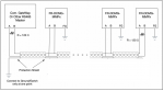
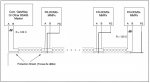
We investigate the situation , we found that there is big AC voltage between the wire A or B and the commun , or A and the PE ground, or the Shield of the RS485 and the PE ground , we mesured up to 143 VAC , this voltage has a fast variation from 1V to 40VAC or 60VAC or 100VAC up to 143VAC (max mesured , the max value follow proportionaly the the power generated by the inverter.

We conclued that this is a 'Noise' in the signal , we make the proper cabling (Shield to the ground in one point) , we did the insulation test of all the equipements we found that everything is ok and probleme still aprear.

We mesured the voltage between two ground wire in different location on the field , we found a potentiel difference up to 24VAC !

I conclude that it's a common mode noise that affect the communication cable.

i'm still searching for a solution to this probleme and also i'm searching for the exactly source of the probleme !
I will be appreciated if someone can help me understand this problem.

Regards.
 
It sounds like there may be improper grounding on the RS-485 network and that you may be measuring voltages with respect to incorrect references. If you truly had over 100V difference between A or B and the common-mode reference, your devices would not survive that (RS-485 allows for only -7 to +12V difference between A or B and common).

How are all of the devices wired together (2 wires, 3 wires, shield, etc.)? Can you provide a diagram?

How are all devices powered and grounded?

Take a look at the Grounding section in the following application note for a diagram of the proper way to wire RS-485 devices together:
http://www.bobtech.ro/get?download=21:rs485-wiring-guidelines

There are several signals to consider in an RS-485 network:
  • RS-485 Noninverting data signal (+)
  • RS-485 Inverting data signal (-)
  • Common-mode reference (COM, REF, GND, Signal Ground/SG, 0V)
  • Cable Shield

You would think the first two are obvious, but not necessarily. Many people see + and - and think it works like a battery's + and - terminals, one is a "send" the other a "return", but this is not the case. RS-485 uses differential signaling, so really both the + and - are "sends" and the common mode-reference is the "return". Basically the - signal is always inverted, but identical to the + signal, when measured with respect to the common-mode reference. The way the RS-485 signal is interpreted is by measuring + with respect to the common-mode reference and subtracting the - with respect to common-mode reference.

All RS-485 devices must share the same common-mode reference. Unfortunately, this is one of the hardest things to accomplish, since it is not always obvious what an RS-485 device's common-mode reference is. And judging by the design of many RS-485 devices on the market, there are several RS-485 device vendors that seem to not understand this. Many RS-485 devices are nonisolated, and therefore, the RS-485 common-mode reference for these devices is the power supply's negative or ground terminal (half-wave rectified 24VAC devices, for example). You need to figure out and understand where the common-mode reference is on each and every one of your RS-485 devices in order to know how to properly wire them together.

As far as shielding, the shielding should be continuous across the entire bus and earthed at one end only (typically at the front-end controller).

You may have one or more devices that are not wired properly or cannot be wired properly. If this happens, then you need to install isolated RS-485 repeater(s) to isolate those devices from the rest of the network.

Start by splitting your network in half and taking voltage measurements. Continue splitting each segment in half until you no longer see issues and can narrow down the problem devices. If possible, take these measurements when there are no devices transmitting on the bus (for example, temporarily remove or disable the master from the network).
 
Hello, thanks for your answer sir,

For the wiring , i have a twisted Shielded pair , so i use the pair wires to connects A, B and i did connect the schield in one point as recommended, but for the common 'C' or 'GND' , i connected to the PE ground terminal of every slave , since i didn't have a third wire, so the ground path in my case is the return path. in attached the schematic diagram.

The voltage that i found is an AC voltage not DC voltage , the RS485 require a common voltage between -7V and 12VDC, in my case the DC voltage between A or B and the comman it's ok (arround 0 VDC) , but the AC voltage is the problem , since i notice that when the AC voltage exced a value (exemple 30 or 27VAC) the communication lost.

I will verify again the RS485 network as you required , i hope that i can some mistakes on the wirings.
 

Attachments

Regardless of whether the voltage is AC or DC, a voltage higher than the specified maximum applied to an RS-485 transceiver can damage it.

While not ideal, using earth ground as the RS-485 common-mode reference is a configuration that can be made to work. However, earth ground is a very noisy ground and you very well may have created a ground loop if other grounding sources (such as power supplies) are already earthed for these devices. It is very important to determine what each device uses as the common-mode reference, if there is a terminal available for it, and if it is isolated from the power supply circuitry. If you would like assistance with this, please provide the vendor and model of all RS-485 devices on your network.

Additionally, when using earth ground as the reference, a resistor (100 ohms) is sometimes used to provide a higher impedance path from the device to ground (this helps reduce ground loop currents if you have inadvertently formed a ground loop in your system), while still ensuring the devices' common-mode references stay within -7V to +7V with respect to one another.

I advise you to read the following application notes:
http://robustdc.com/download/index.php?file=AN005.pdf
https://www2.htw-dresden.de/~huhle/ArtScienceRS485.pdf

As another suggestion, try temporarily removing all 120 ohm termination from the network. Depending on baud rate and length of cable used, termination may not be necessary. Since you say you are measuring 0VDC between A and B, that seems to indicate that the termination resistors are essentially shorting out the network. An RS-485 bus should have at least 200mVDC between A and B when idle (no devices transmitting).

If you are using a high baud rate (above 9600) and your the total length of your wiring is long (over 1,000ft or 300m), then termination may be required. If so, you may need to add network biasing resistors between 5V and A and between ground and B. However, doing this does reduces the number of devices (unit loads) you can have on the network.

Take a look at this article for reference:
https://blog.opto22.com/optoblog/rs-485-to-terminate-bias-or-both
 
I found the device:
https://www.fonrich.com/static/dcb009b26ccfd808a22b4f197c380396/FR-DCMG-MMPP_UM_EN_V1.0.pdf

It seems that the FG terminal is used as the RS-485 common-mode reference for these devices. Is this the terminal you have grounded to the building's grounding system for each device?

With the device powered off, check continuity between the FG terminal and the PV- (DC power supply terminal). This will tell you if the RS-485 circuitry is isolated from the power supply circuitry. If there is continuity, check how your DC power supply is grounded, if at all. If so, you have two ground points for the devices and have created a ground loop.

You should also check continuity between FG and the SG terminals (temp sensor and digital input ground terminal). If there is continuity between these, you also need to check the grounding of sensors connected to the SG terminals for additional ground loop sources.
 
Hello @jschulze thank you for your participation , i appreciate a lot your advice, that's can help me to solve the probleme.

Since i have a ground potentiel difference , making connection for The 'FG' and the ground is not recommended in my case , i think to connect the FG to the ground you must have an equipotentiel ground.

What i did , i isolate the FG from the ground, and since i don't have the third wire , i used the Shield to connect all the FG or 'Commun' like that i ensure that i have the same signal reference in all equipement. i didn' connect the Shield to the ground, i test with this solution and congratulation everythings work fine ! the voltage between the A and commun disapear (around 1v to 2v).
 

Attachments

The main issue is you cant use instrument wire for communication. It stores voltage... you can get away with using it if the baud rate is low and your poll rate is slow (1 device per second). Also the wiring method is very critical- it need to be a buss connection and not a star for example.
 
Top