Facebook
 Google
 GitHub
 Linkedin
hello guys.
We have serious problems with the online entry of the D / G No3 breaker, it enters manually or automatically for a few seconds, disconnecting urgently. The main breaker was disassembled, checking contacts and mechanisms, it was mounted and the failure continued, so it was decided to exchange the breaker from one generator to another without any result, thus ruling out that the problem is with the main breaker.
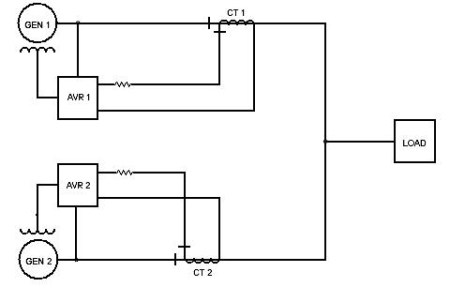
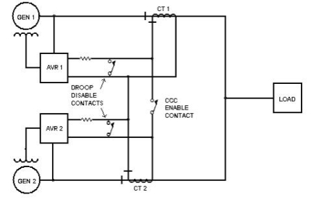
The revision of all the circuits and protections of the system is continued, the diode bank of the exciter is measured, the current of the reactor, the card is extracted from the ESM-1102 relay module, and it is checked, cleaned and reassembled. Current and voltage transformers are reviewed.
We shut down the ship and this alternator went online, which does not hold the load at all. The generator was online with the lights, and when we try to start a pump the diesel generator went offline and shutdown.
In the first reactive load that is given to the Diesel generator, it goes offline immediately, so the problem is not that it does not go online but that it does not hold the load after entering. That is why we think that the problem is with the alternator. When we try to give some load to D/G number 3 with auto shift on main Switch Board, the process start and once the D/G 3 receive a load the breaker goes out and then D/G 3 go out of line. We discard the breaker because the ACB of D/G 3 was change to D/G 2 and it’s working property.
We extract the ACB and we can see in the bakelite evidence of electric arc, not normal. We disconnect the cables on Generator (R S T stator coil) and use an insulation tester. The insulation tester result on Terminals R S T of the generator was about 0.5 Mohms. In my opinion it is too low.
We also see that in ACB there is an error RPT(Reverse Power Trip) led is on(red). I've been reading your post about reverse power and we have to check the fuel injection and the governor.
We check some relays that are part of the control circuit of synchronization circuit but nothing happens. we discarded the synchronizer because the other generators go online without problems.
i hope receive your kind opinions.
best regards
Abel
We have serious problems with the online entry of the D / G No3 breaker, it enters manually or automatically for a few seconds, disconnecting urgently. The main breaker was disassembled, checking contacts and mechanisms, it was mounted and the failure continued, so it was decided to exchange the breaker from one generator to another without any result, thus ruling out that the problem is with the main breaker.
The revision of all the circuits and protections of the system is continued, the diode bank of the exciter is measured, the current of the reactor, the card is extracted from the ESM-1102 relay module, and it is checked, cleaned and reassembled. Current and voltage transformers are reviewed.
We shut down the ship and this alternator went online, which does not hold the load at all. The generator was online with the lights, and when we try to start a pump the diesel generator went offline and shutdown.
In the first reactive load that is given to the Diesel generator, it goes offline immediately, so the problem is not that it does not go online but that it does not hold the load after entering. That is why we think that the problem is with the alternator. When we try to give some load to D/G number 3 with auto shift on main Switch Board, the process start and once the D/G 3 receive a load the breaker goes out and then D/G 3 go out of line. We discard the breaker because the ACB of D/G 3 was change to D/G 2 and it’s working property.
We extract the ACB and we can see in the bakelite evidence of electric arc, not normal. We disconnect the cables on Generator (R S T stator coil) and use an insulation tester. The insulation tester result on Terminals R S T of the generator was about 0.5 Mohms. In my opinion it is too low.
We also see that in ACB there is an error RPT(Reverse Power Trip) led is on(red). I've been reading your post about reverse power and we have to check the fuel injection and the governor.
We check some relays that are part of the control circuit of synchronization circuit but nothing happens. we discarded the synchronizer because the other generators go online without problems.
i hope receive your kind opinions.
best regards
Abel