servovalve turbine GE 3002

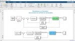
Je cherche à déterminer la fonction de transfert du servovalve de la Vanne Contrôle Gaz (GCV) qui contrôle le débit de gaz vers les chambres à combustion. Ce servovalve entraine un vérin hydraulique qui actionne la GCV. le signal de retour est récupérer par des LVDT (transducteur à déplacement linéaire variable). 0% de course --> 0 Vac (Vanne complètement fermée)
100% de course --> 5 Vac (Vanne complètement ouverte).

Je n'arrive pas a identifier la plage du signal qui attaque le servovalve a l'entrée. Serait-il le retour des LVDT ( 0 - 5 V).
 
No problem, I'm glad you liked it. Have a good read and ask any questions later. I have worked on MKV from it's very beginning to it's end as a GE Field Engineer
 
I found the attached document among some old documents, it is for MS3002 and, I think, was originally written for MKII Speedtronic but the control principle is still the same. Two shaft control is a little difficult especially the 2nd. Stg Nozzle control as everything is very interactive, Load control from the LP turbine and Speed control from thr HP.
Again have a read and see if you have any question. Many 3002 machines in the past from Siberian gas pipeline and Sonatrach, Algeria.
 

Attachments

Merci pour le deuxième document.
J'ai réalisé une interface graphique a l'aide de la plate-forme Simulink de Matlab pour modéliser et simuler les boucles de contrôle du système combustible. Pour la vanne SRV, on a 2 boucles en cascade. La boucle de pression P2 en série avec celle de la position de la vanne. Pour la vanne GCV, on a seulement la boucle de position. Il me reste quelques données pour finaliser ce travail.
Je vous joins un aperçu.
 

Attachments

It's a good idea to make a plan for items of Flow diagrams so you can understand better. Flow diagram understanding is the biggest help in trouble shooting for all disciplins ( Operations, Maintenance, etc). Study the drawings, identify the components and watch the systems in good operation to help identify problems.
Servo drive systems can be a big item of problems, servo valves do fail so keep a stock of good spares ( Be careful, all servos look the same but they are not, they are different flow rates. Look at the P-number at the end of the part No.)
Increased Servo failures can be caused by poor lubricating oil quality, check you Lube Oil regularly and make any adjustments to recover good oil quality. Servo valve clearances are very small, only in microns, so the servo valve can act like a filter. Check servo operation when you have downtime at least for steady, acurate stroke, it can save you unplanned downtime. Remember, to replace a servo,you need to get the Lube/Hydraulic Oil off, so, on a Hot machine, you can need a whole shift to get the servo replaced (Operations Managers don't like this !!)
 
Wow! These came from a GE internal SupportCentral site which was taken down more than 10 years ago. This is a blast from the past.

They are as relevant today as they were ten years ago. Thanks for sharing, HamsterKing!
 
How to determine the gas flow feeding the combustion chambers knowing the pressure and FSR values. In the MarkVI documentation, GE gives the following relationship for gaseous fuel. Flow = pressure X FSR; it is the pressure P2 which is regulated by the speed NHP or P3 downstream of GCV. What would be the unit of flow?
 

Attachments

Guerini,

P2 pressure is a function of HP speed:

P2 Pressure Reference=(TNH*FPKGNG)+FPKGNO

FPRG = Fuel Pressure (P2 Pressure) Reference-Gas, in psig
TNH = HP speed, in percent of rated
FPKGNG = P2 Pressure Reference (Gain), in psig per percent speed
FPKGNO = P2 Pressure Reference (Offset), in psig

This is all explained in the Control Specification (System Settings) document provided with each Mark* turbine control system, and can be seen by looking at the logic/sequencing/application code running in the Mark* being used for the turbine control. It has also been explained MANY times before on Control.com, and can be found using the 'Search' feature at the top of every Control.com webpage.

GE doesn't usually monitor gas fuel flow-rate; it's usually only done for developing a water- or steam-injection flow-rate reference, and it's ONLY for monitoring--it's almost NEVER used for control purposes. There is no air/fuel or fuel/air monitoring in most GE-design heavy duty gas turbines (though I think that's changing as I write with the newer HA models).

GE has provided a metering tube and orifice on many GE-design heavy duty gas turbines for monitoring gas fuel flow-rates--and MANY people think it is a revenue-quality metering system. IT IS NOT. It is for indication and monitoring only--except when it's used for developing water/steam-injection flow-rate references.

Finally in the Control Specification document there are some tables. in Sect. 05.02.nn, I believe, which give TYPICAL fuel flow-rates at various operating conditions (firing; full speed; 25% load; 50% load; 75% load; 100% load)--but, again, these are just typical values and the actual fuel flow rates are NOT compared to these in the control scheme.

It would appear you are modeling an MS-3002 machine for some purpose (training?). Best of luck in your endeavour.
 
Strangely GE Speedtronic control systems, all the way back to MKI Speedtronic, don't measure flow in their Fuel Gas control systems. The flow control is done by:-
1) Maintaining P2 pressure by modulating the SRV, this value is set by a Fuel Gas analysis at the time of specifying the machine, a good spec. should give SRV stroke at around 80% at 100% ISO load.
2) Modulating GCV to maintain demanded load.
So, when more or less load is required, GCV modulates and, of course P2 pressure changes so SRV modulates to maintain P2 pressure.
It's a pretty unusual way to control the flow of fuel compared to Basic Instrumention Flow Control which usually has a Flow Meter but it works very well and is very accurate.
I've never seen your GE formula Flow = pressure X FSR before , for sure the GCV metering valve has a shaped flow plug which will regulate a flow at constant P2 pressure (Again set by a Fuel Gas analysis) so the GCV doesn't run out of stroke over the load range. To get a unit of flow you would need to see the GCV Spec. to get Flow vs Inlet Pressure vs FSR (Go look in your 20+ volumes of manuals, nice job !)
Normally, if you want a recordable flow, you can install a reasonably cheap Flow Meter at the SRV inlet which will give you something to look at. If you want something for accountable purposes, Fuel Payments, Environmental Analysis, etc you will need to get a Certified and calibrated Flow Meter which will cost a lot more.
Have a go at using the formula and see what you get, let me know the answer, I'm intested.
I did work on one job where they got a second, totally different Fuel Gas. and the system couldn't handle it. They had to do some fancy engineering to make it work. So, keep a good check on your fuel gas analysis, if it changes things can change.

A very good question. Good Luck and keep in touch.

Cheers for now

CSA, you got in before me, while I was writing. Now you have 2 answers Guerini
 
I asked this question only to try to correlate the equation that relates the rate of opening of the GCV valve to the FSR and the flow that enters the combustion chambers.
On the other hand, the equation which links the pressure P2 to the speed NHP is important for the simulation of the fuel control loop (SRV). As shown in flow diagrams.
I made a calculation sketch and I ask your opinion. I am doing this work selflessly to create a simulation platform to assist maintenance people and those who are interested.
Concerning the reference of GE relating to the calculation of the flow, I found difficulties for the sending of the document in question.
For this, I send you my email.
[email protected]

See you next time.
 

Attachments

Guerini,

As glenmorangie said--the secondary purpose of the Stop/Ratio Valve is to control the pressure upstream of the GCV when the unit is at rated speed (which is a range in the case of a MS-3002 mechanical drive turbine). This allows the fuel flow through the GCV to be more linear (proportional to) GCV valve stroke. Without this two-valve arrangement controlling P2 pressure it would be necessary to have an equal-percentage trim valve (pretty expensive valve!) or to have some kind of difficult to understand valve linearization curves. This two-valve arrangement of controlling P2 pressure at rated speed is a simple and effective means of using more reasonably-priced control valves to accomplish a simple means of trying to linearize flow versus position when at rated speed.

There are other things the Stop/Ratio Valve accomplishes during firing and acceleration, and, of course, it is primarily a STOP valve for gas fuel.

Your diagram seems to be good. You have the idea that the SRV is a pressure-control valve with a position-control loop and that's a little difficult for people to understand because they always want to equate SRV position with load. The SRV moves to WHATEVER POSITION IS NECESSARY to make the actual P2 pressure equal to the P2 pressure reference. If the actual P2 pressure is equal to the P2 pressure reference then the output of the first summing junction (for pressure) is zero--which is fed to the second summing junction (position), and if the input to the position summing junction is zero then the valve doesn't need to move (because the actual P2 pressure is equal to the P2 pressure reference at this SRV position). It's as simple as that.

There's no rocket science here--contrary to popular belief. The outer position loop is simply for added stability--since in a digital Mark* the servo-valve output current (from the pressure regulator) changes at the rate of from 100- to 128 times per second (which isn't as fast as the old analog circuits--but it's still pretty darn fast). The outer position has nothing to do with anything (well--there's that stoopud STARTUP FUEL FLOW EXCESSIVE alarm, which doesn't actually monitor or compare fuel flow to anything...!). The SRV is going to move to whatever position it needs to be in order to make the actual P2 pressure equal to the P2 pressure reference--and if it doesn't need to change position to do that, it won't.

Again, it looks like you've got the basics down pretty well.
 
I neglected to comment on your reasoning for asking this question--which you said was to "...correlate the equation that relates the rate of opening of the GCV valve to the FSR and the flow that enters the combustion chambers."

Some people (correctly) refer to the GCV as the FSR valve--because the reference for GCV position comes from FSR (Fuel Stroke Reference--which is a way of saying "gas control valve opening reference"). If FSR is 20%, then the GCV should be at approximately 20% stroke (opening). If FSR is 65%, then the GCV should be at approximately 65% stroke (opening).

Why:? Droop Speed Control determines FSRN--Speed Control FSR, which is the FSR from FSNL (Full Speed-No Load) to Base Load, everywhere between FSNL and Base Load. Now this is true for generator drives; it's been a LONG time since I've looked at a Mark* control system for a two-shaft mechanical drive system, but I think it's still basically true (one of the beauties of GE turbine control systems--the "sameness" they have across applications and Frame sizes!). FSRN has been covered MANY times before on Control.com. The only difference I can see is that instead of TNR for a single-shaft generator drive is for the HP shaft; TNR for a two-shaft mechanical drive unit is for the LP shaft (SOMETIMES called TNRL--and sometimes not (this is one of the inconsistencies that can be annoying about GE heavy duty gas turbines and controls...!).

Anyway, when the P2 pressure reference is as it should be for a machine and the fuel matches the specifications used for deriving the control parameters (including P2 pressure reference), when the GCV (at rated speed!) is at a value nearly equal to FSR then that amount of total maximum expected fuel will be flowing to the combustors. (This is where the "Expected Fuel Characteristics" of the Control Specifications is SO helpful for designing simulations that are close to expected operating parameters.) So if FSR is 37.5% and the GCV is at approximately 37.5% of stroke (opening) then approximately 37.5% of total expected fuel flow (at ISO conditions) will be flowing into the combustors. If FSR is 67% and the unit is NOT at Base Load then the total fuel flow-rate to the combustors will be 67% of total expected maximum fuel flow to the unit (at ISO conditions).

I hope this doesn't cause a lot of confusion for a MS-3002 control scheme. I think you will see it's very similar to a MS-5001 or MS-7001 control scheme (again because of the "sameness" of GE control systems).
 
Top