SPEEDTRONIC MARK V 3D Table: How to Get Table Values?

Hey guys,
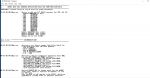
I am working (remotely) on a GE Frame 7EA (MS7001EA) DLN1 Machine, and there is a table used for a linear interpolator in the logic. In the Mark VIe you can export the table to a PDF within Toolbox, but not sure about the Mark V. Was hoping I could get some instruction here on how to obtain those curve values.

I cannot directly access the running controller, as I am remote, but I do have all of the "Unit 1" files on my laptop, and so I haven't had any trouble getting curve values until I got to this 3D Table. I also have site maintenance personnel available to gather information from the running controller for me as required.

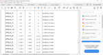
This table uses CSGV and TNHCOR to cross-tabulate a Compressor Ratio Limit, but I cannot find anything in the site files such as a pdf of the table (Which usually S/U Engineers create for posterity).

CXLIM7EA.jpg
 

Attachments

Hi

I have a Frame B CSP file showing that CPRLIM 3D table/curve better detailed than the one that you shared.

I know that is not same unit frame but it can highligh you some points that you lookin for...

Cheers,
James
 
I have checked every file in my Unit folder. The constants from your csp (CPRLIM_X, Y & Z) don't exist in my CONST_Q, nor do any array values that would be used to build that particular curve. I am completely at a loss. Surely I will be able to view the "3D Table" values when I get to the site using ToolboxST I imagine
 
Bump...I could really use something here. I know all the frames have a CPRLIM curve, if I can't get the lookup table, just some means of plotting a reasonable CPRLIM would be great
 
I can't be much help on this but have been following it. We have the same block in our MarkV's and I cannot find the 3D table either anywhere. I went online with unit and still cannot see it in the rung display. I looked in control spec and it has a brief description of how it works and a chart with curves, but no numbers are on the chart. The description just states that it looks at IGV angle and Speed and software had been developed to control compressor bleed to limit compressor ratio. Not sure if this is something that is in EEPROM, probably not but I don't know. I can't find any contants that relate to this either that are mentioned above. Our unit is F frame with Mark V. If it's a MarkV your working with I don't believe you will able to use Toolbox ST.
 
HamsterKing,

[To anyone else reading my post here--this is ONLY for Mark V. Not any other digital Mark* turbine control system.]

So, are you saying that the CXLIM7EA block appears on the CSP (printout AND electronic copy (CSP.PRN) BUT that when you go on-line with Rung Display it doesn't show up?

Because Rung Display (for Mark V) "animates" the CSP Segment Source files on the <I> or HMI--NOT what's actually in the Mark V EEPROM. (Just a little "feature" of Mark V...!) So, if the CSP Segment Source files on the <I> or HMI you're using Rung Display haven't been updated to the latest and greatest CSP Segment Source files which were used to create the download CSP partition files that were actually downloaded to the Mark V EEPROM then Rung Display will not be accurate.

I have to believe that if the block is actually in a CSP Segment Source file (which are used to produce CSP.PRN) then there is a rung number associated with the block--and that if it didn't appear in Rung Display there must be a "missing" rung number.?.?.? So, from the original post the Rung Number is 232, and if it did not appear in Rung Display then the rung numbering would "jump" from 231 to 233. But that's just a SWAG.

Now, the ASCII representation of the block should be found in the PROM subdirectory and have a filename very close to CXLIM7EA (I can't recall what the filename extension would be). BUT, THAT is ONLY the ASCII text "drawing" of the block--and NOTHING more.

If you open the CSP Editor and open the CSP Segment Source file where the rung appears then you should only see a "tile" representation of CXLIM7EA--BUT you should see the names of the parameters passed to the file (such as CSGV) and MAYBE the names of the Control Constant arrays for the block to use.

This is very confusing--to me. I have seen something similar when GE Salem tried to "detail" the flame detector intensity deadbands in a block. The actual functionality is in TCEA PROM, but from the block they used it the functionality was in the CSP. I think they stopped that practice after a year or so, but there are probably still some older units with older PROMsets out there that still have that representation.

I ALSO notice in the original post that Rung Number 233 "Compressor Pressure Ratio Operating Limit"--just NOT for a 7EA.?.?.? The original poster doesn't mention "problems" with that rung, and neither do you, HamsterKing.

I don't have any Mark V software I can look at, and I don't recall ever seeing a 3D Table in a Mark V CSP--I may be wrong (I've been wrong MANY times before (just ask my wife...!)) but as I mull this thread over I don't recall any 3D tables. This was all done in PRIMITIVE blocks (ADD; SUBTRACT; COMPARE; etc.). There WAS comp op limit protection--it was just done in PRIMITIVE blocks.

Finally, I have to believe that any Control Constant(s) used for the CXLIM7EA block would be arrays--meaning there would be multiple values with the same "basic" name (think TTKn_I, for example, where "n" is an integer 0 through 7--so there are eight total values for TTKn_I).

Anyway, that's all I got or can add. If you can do a little more description of what's in the CSP Segment Source file and what you're seeing on Rung Display--and if the CSP Segment Source files on the <I> or HMI you're using Rung Display on are the same as on any other <I> or HMI connected to the same Mark V, that would be helpful.
 
Now, the ASCII representation of the block should be found in the PROM subdirectory and have a filename very close to CXLIM7EA (I can't recall what the filename extension would be). BUT, THAT is ONLY the ASCII text "drawing" of the block--and NOTHING more.
It is a .PIC file.

I ALSO notice in the original post that Rung Number 233 "Compressor Pressure Ratio Operating Limit"--just NOT for a 7EA.?.?.? The original poster doesn't mention "problems" with that rung, and neither do you, HamsterKing.
Rung 233 is jus a BBL Proportional + Integral Controller that uses CPRLIM as the "SP" and CPR as PV.

Finally, I have to believe that any Control Constant(s) used for the CXLIM7EA block would be arrays--meaning there would be multiple values with the same "basic" name (think TTKn_I, for example, where "n" is an integer 0 through 7--so there are eight total values for TTKn_I).
Well, I have gone through CONST_Q looking for something like that. The problem is, it isn't a simple curve like a F(x), it is a table lookup function (apparently). There should be X, Y, Z coordinate trio instead of a typical XY Pair.

I will continue to pour through what I have available, and I will be on site in a couple of months and perhaps I will have better luck that the engineering group over there.
I am just trying to reliably reproduce the CSPLIM curve, I never expected it to be this much trouble.

Thank you for your response, and to everyone else who has responded,

Casey
 
I can't be much help on this but have been following it. We have the same block in our MarkV's and I cannot find the 3D table either anywhere. I went online with unit and still cannot see it in the rung display. I looked in control spec and it has a brief description of how it works and a chart with curves, but no numbers are on the chart. The description just states that it looks at IGV angle and Speed and software had been developed to control compressor bleed to limit compressor ratio. Not sure if this is something that is in EEPROM, probably not but I don't know. I can't find any contants that relate to this either that are mentioned above. Our unit is F frame with Mark V. If it's a MarkV your working with I don't believe you will able to use Toolbox ST.
Yeah, you are seeing the same thing we are. And yeah, I was just reaching hoping toolboxST would maybe work.

The curve they show in Control Settings document is great except it has NO VALUES.

CPRLIM.jpg
 
CSA;

I think my previous post was misleading. I can see the block in the dynamic display as well as the csp.prn. I was trying to communicate that I cannot see where the values for the array come from. casey.little seemed hopeful he would find the table values in the live logic when he got to the site he is working at. I am using the server for the unit I was looking at, where all the downloads are done from for the unit and am confident the correct PROMS are in the HMI.
I would expect to see values for a controls constant as you said with a _n to make up the data table. I would actually expect to see these constants in the CSP.prn as well, listed below the block.
I have not looked at the block in CSP editor yet, but may have a look to see if they are there.
I do not have an issue at my site, I was just reading the original posters question and had a look to see if I could help, that block doesn't exist in the applications manual either which made me more curious.
Controlsguy25 seems to have found constants, but I do not have those constants and it would appear the original poster does not either. I have browsed through the whole constant file and do not see any constant that would make me think are used in this block.
 
Casey,

OEMs typically keep compressor maps confidential and rarely make the information available - even for users. I'm not very familiar with how password protection and encryption works on MarkV software - But with our MarkVe controls, these big block macros for the compressor ratio limits all require a privilege level 3 password to view - the information is even encrypted when viewing the library macro and program .xml files as an admin.

Our CXLIMXXXX block only displays the same two variables (CSGV and TNHCOR) - and you can not drill down to see any further without the password. The other pin connection configurations are set with visibility = never. These variables are 'krlim' - CPR ratio limit array, 'kgv' IGV pos array and 'khcor' the corrected speed array. There is also a cprlim min and max variable labeled 'krlimmn' and 'krlimmx' if I recall correctly. Viewing the connected variables for the block only displays the first value for these arrays (ex. kgv = 40, khcor=90, krlim 8.0 for example). The rest of the values are hidden.

These variables seem to act as constants but aren't configured as such, thus they don't show up in our constants list. Nor are they listed in any of the system variable, global variables, io, egd, or ram reports. Even when the whole system is searched, the variables are only listed as used with this block and attempting to view them prompts the privilege request. In our case they don't appear to be written from anywhere, they are simply a constant with an array of comma separated values.

After spending a shift or two killing time in the control room in frustration that the values were obfuscated, I finally found a way to view the 'initial values' for these variables along with the internal block descriptions and pin names without needing the password (which no one on our site has apparently.. also none of the standard ones work), which enabled me to determine which blocks & pins are used the input values. Our control system macro library has a variety of "aftermarket" macros for different turbines, including the 7EA (I have no idea if it's applicable or correct for your application) and they all use the "Double Analog linear Interpolation" block DALIP00&1. More information on these blocks can be found in GEH-6195 for the MarkV.

For CXLIM_7EA,I can see that in my control system, 'krlim' has 64 values, 'khcor' and 'kgv' both have 8 comma separated values. I can send you these values for educational purposes but I must insist that I have no idea if they are actually applicable for your 7EA turbine compressor - The only revision notes I can see on this particular block state "Updated curves for CXLIM_7EA per DCI 02029059"

Below is an example of what the curves from the CXLIM_7EA block in our control library looks like, I have cleared some of the information for my sake. (Again, I have no idea if this is correct, I don't have access to any 7EA historical data to compare. The upper IGV angle curves look different compared to our 7FA turbine curves which don't cross each other like shown in the 7EA numbers *

If you have access to historical PI data which includes IGV angle, Corrected Speed and CPRLIM you could likely make your own curves based on the recorded data in excel... - The curve I created for our units were within 1% of the actual values. A bilinear interpolation formula for the MarkV array formula array values can be found here https://engineerexcel.com/bilinear-interpolation-excel/ if you wish to check your results versus the controls.


1642990518727.png
 
For CXLIM_7EA,I can see that in my control system, 'krlim' has 64 values, 'khcor' and 'kgv' both have 8 comma separated values. I can send you these values for educational purposes but I must insist that I have no idea if they are actually applicable for your 7EA turbine compressor - The only revision notes I can see on this particular block state "Updated curves for CXLIM_7EA per DCI 02029059"
Please please share them with me. I do intend to grab historical data to review the curve, but I would really like to see how that compares to the numbers from your DALI.

I will PM you
 
All;
I looked a little more and think the values in the MarkV are stored in the prom chip on possibly the SDCC card or other card. Attached is a pic of the PROM_REV file and it shows those curve blocks in the prom revisions and lists chip revision numbers.

This possibly goes along with what MattyIce is saying that the values are not shared and proprietary.
 

Attachments

Top