Facebook
 Google
 GitHub
 Linkedin
hello everywhere
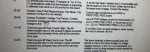
I have a big problem in our turbine framme 5 MS5002C controled by MARK VI
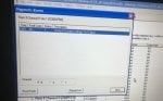
when i start the machine,in firing i have the alarm-srv not following trip-
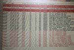
i checked all the cards,i was found a real alarm in VPRO module -code 40: contact exitation voltage failure-in the diagnostic to chech this alarm,its mean -loss of P125 voltage caused by disconnection of JH1 to TREG,or disconnect of JX1,JY1,JZ1 on TREG Tto J3 on VPRO- i checked it,i find 28V in this alimentation of JH1 and i checked the jumper JX1,JY1,JZ1 that it,s in good function.
Please can someone with experience about this problem help me out with the actual issue and how to solve it.
I have a big problem in our turbine framme 5 MS5002C controled by MARK VI
when i start the machine,in firing i have the alarm-srv not following trip-
i checked all the cards,i was found a real alarm in VPRO module -code 40: contact exitation voltage failure-in the diagnostic to chech this alarm,its mean -loss of P125 voltage caused by disconnection of JH1 to TREG,or disconnect of JX1,JY1,JZ1 on TREG Tto J3 on VPRO- i checked it,i find 28V in this alimentation of JH1 and i checked the jumper JX1,JY1,JZ1 that it,s in good function.
Please can someone with experience about this problem help me out with the actual issue and how to solve it.