Updating Control Constant on Mark V and Mark VI

Hello Team,
This might be a strange question.....What is the possibility of replacing the entire control constant file in a Mark V and Mark VI control system for a Frame 5 and the procedure of doing in both systems? and What are the pitfalls in doing it?. The replacement CONST files are from identical Mark V and Mark VI units.
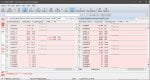
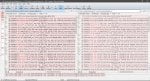
 
cheedee,

Strange question, indeed.

Yes; it's possible. Relatively easy for the Mark V, a little more difficult for the Mark IV.

What formats are the replacement files in? I presume for the Mark V you have CONST_Q.SRC and CONST_B.SRC, (or CONST_C.CRC) files.

The Mark VI would be a different beast, I think. Probably depends on the version of Toolbox (Legacy Toolbox).

And, while the turbines may be "identical" are the control systems the files are being taken from identical???

I would think the easier thing to do would be to use an ASCII file comparison utility to compare the two Mark V Control Constant files and the two Mark VI Control Constant files and look for differences. It would probably be necessary to sort the four files alphanumerically first before trying to compare them. Back when I was commissioning Mark Vs GE used Beyond Compare from www.scootersoftware.com. It was fast and easy. There are other text file comparison tools that will probably do the same thing and just as easily.

So, The pitfalls I see--without knowing a LOT more about the turbines the files are coming from and going to--are that the software is not identical. Sure, all GE-design heavy duty gas turbines look basically alike, and have similar components and auxiliaries--but I have worked at many sites where a turbine was installed and commissioned, and then a year or two later another turbine of the same Frame size, burning the same fuels, was installed and commissioned with the "same" turbine control system. But, it wasn't really the same. There were, for example, at least four versions of Mark V panels, and tens of versions of different Mark V gas turbine PROMsets and firmware. They did the sane functions--controlling and protecting the turbines, but there were differences--some subtle and some not so subtle. I've even seen multiple Frame 5 and Frame 7EA and Frame 9E and Frame 7FA turbines installed and commissioned at the same time (over a few months) that had different controls parameters (Control Constants)--and they had different Control Constants, because every turbine is not the same (identical).

Anyway, it's more than likely doable. Is it advisable? Certainly not, not without understanding what the differences are and why. And, certainly, just copying one file from an "identical" turbine and control system to another "identical" turbine and control system without doing some research and analysis is definitely not recommended.

But, I have been rightly accused of being a turbine controls conservative.

Your mileage may vary.

Best of luck!

Write back and let us know how this works for you.
 
As all, thanks CSA for your help!! (y) My mileage definitely is less than yours. Thanks for the comparison software, using it now for the analysis
I want to crave your indulgence on the questions am about to ask;
1. On Mark VI in particular, what is the process for replacing the CONST file?
2. On Mark V, will copying and pasting the new CONST file in drive F: and executing an EEPROM download change the file?
3. Can all these be done while the GT is running?
4. A little digression, what constants affect the percentage opening of the GCV(apart from FPKGNG,FPKGNO)?
4b. Is there a standard or average P2 pressure for MS5001PA?

Thanks for bearing with my wild questions.
 

Attachments

cheedee,

Are you calling me "old"??? (I guess I'm approaching that age, but I sure don't feel like it too much yet.)

Or are you just saying I've been rode hard and put away wet (a reference to poor treatment of horses used in the Pony Express carrying mail across the USA in the 1800's)?

Anyway, I do have a few miles under my belt....

I'm not sure what exactly the screenshot is supposed to tell us, but it's as I suspected--if it's for two Mark V CONST_Q.SRC files from "identical" machines--they ain't (identical). Not by any stretch of the imagination.

The topic of source files and downloads for Mark V configuration has been covered MANY times on Control.com in the past. Here's a very brief summary...

The operator interface has multiple ASCII text files that are used to configure a Mark V turbine control panel for a particular turbine and application and site and auxiliaries. To modify the configuration, one has to modify the ASCII text files.

The ASCII text files must then be compiled into a non-executable format that the operating system of the Mark V turbine control panel processors can understand.

The EEPROM Downloader function can then be used to download one, two, five or all (NEVER use ALL!!!) configuration files to the EEPROM chip in each of the Mark V processors.

To make the changes effective, it is necessary to re-boot each of the processors which the new compiled, configuration files were downloaded to (that's because the Mark V processors use information in RAM--not from EEPROM, and to get the information into the RAM from EEPROM it's necessary to re-boot the processor(s)).

So, configuration files exist in four places: two on the operator interface (an ASCII text version, and a compiled version), in Mark V processor EEPROM, and in Mark V processor RAM. Again, to get changes to take effect, one has to make the change to the ASCII text file, compile the ASCII text file, download the compiled file to EEPROM, then re-boot the Mark V processor to get the compiled file information into Mark V RAM where the microprocessor can use it to properly control and protect the turbine and driven device and auxiliaries.

There are a couple of "unique" sets of files--of which Control Constant are one. (The other is I/O Configuration--which is a totally different story and slightly different set of circumstances.) Control Constants can (generally) be changed directly in Mark V RAM, using the Control Constants Adjust Display. This can be done when the unit is not running or when the unit is running. (When the unit is running the ramp rate for changes to real values is limited to prevent "shocking" the control system.) Older versions of Mark V operating systems COULD NOT copy Control Constant changes from RAM to EEPROM using the Control Constant Adjust Display--newer versions of Mark V operating system software could (copy Control Constant changes from RAM to EEPROM). BUT, to change the Control Constant value in the ASCII text file on the operator interface, someone has to manually edit the ASCII text file--and then someone has to manually compile the file.

SO, it's possible--and it happens FAR TOO OFTEN--that Control Constant values in RAM get changed, BUT the values of those same Control Constants never get changed in EEPROM, or in the ASCII text file or the compiled file on the operator interface. Or, on newer Mark Vs the value of a changed Control Constant gets updated in EEPROM (using the Control Constants Adjust Display), but never gets changed in the ASCII text file or the compiled file on the operator interface.

It sounds like someone is questioning the values of Control Constants currently loaded into RAM in a running Mark V and wants to try to quickly change them to something which works on another "identical" (similar!) GE-design heavy duty gas turbine. And, if what I see in the screenshot is what's happening, one of those files looks like it's for a SIMPLEX Mark V and the other for a TMR Mark V (which require different configuration values and Control Constants). At the very least, it seems the vibration sensors are not the same configuration (redundancy) in the two files, as well as the exhaust T/C configurations. This is a BAD IDEA, to put it very mildly.

Trying to compare two CONST_Q.SRC files to determine what the differences are is NOT going to be very productive--UNLESS you can GUARANTEE the values in CONST_Q.SRC exactly match the values in the Mark V RAM. And, there's no real way to do that. You can upload Control Constants from the Mark V EEPROM (but NOT RAM!) to the operator interface, but there's not way to reverse compile the file back into an ASCII text version. And, without an excellent knowledge of Intel hex format files it would be VERY difficult to compare two compiled files and know what the differences are.
 
Now, to switch to the Mark VI.... I've never actually done this before, and I'm not sure I would even try it myself. I was thinking it might be possible to export the Control Constant values to a comma-separated value (.csv) file, and then compare the files and reconcile any changes, and then take the reconciled file and import it back into the Mark VI. But, I think that would only work on one or two versions of Toolbox, and probably not all. There are other kinds of ASCII text files (.tre files, I think) that can be created from Toolbox and edited and then "re-loaded"--but I would still be reluctant to do it myself. And NEVER on a running turbine!

The Mark VI Control Constant modification situation is similar, but slightly different. One uses Toolbox to look at running values of Control Constants (in Mark VI RAM), and also in EEPROM. And, there's the whole "equal" configuration thing to take into account (which means the "pin" definition of the Control Constant versus the running value in the Mark VI). When you look at Control Constants in a running Mark VI using Toolbox, if there is an unequal sign next to the Control Constant name (or value--I can't remember exactly) it means the RAM value and EEPROM value are not the same. And, if someone changed a RAM value of a Control Constant but didn't update the EEPROM value then the next time the processor gets re-booted the previous value of the Control Constant will be loaded into RAM. OR, if someone didn't ALSO change the Toolbox .m6b "pin" definition Control Constant value, then if the Mark VI application code gets downloaded to the Mark VI the pin definition value will get downloaded. (The pin definition value of a Mark VI Control Constant is like the CONST_Q.SRC value. It has to get changed when a "permanent" change is being made to a Control Constant. Older versions of Toolbox had to be manually modified; newer versions could upload EEPROM values to the .m6b file.) [The Mark VI doesn't really have ASCII text files and compiled files like the Mark V has on the Mark V operator interface. It just has the .m6b file, which is the "single" repository for all the configuration information, the attempt at not having all of the individual ASCII text- and compiled files the Mark V had. All of those Mark V files drove people crazy--but mostly because it was a poor system that was never properly documented from the get-go. There are descriptions in the various GE Mark V manuals, but one has to really read and understand what is being described--which is always the BEST idea anyway!--to get a sense of all of the intricacies of the system.]

ISN'T THIS FUN???!!!?!?!?!!???!!!

No; I didn't think so.

You would need to tell us a LOT MORE about the unit that is "needing" the Control Constant change, and where the Control Constants you want to use came from. A LOT MORE!!! And even then, I would be extremely reluctant to try to help via this forum. It's simply too risky. It's possible, but it's too risky without being onsite and understanding a lot more about the situation and circumstances and where the files to be downloaded to the Mark*'s came from.

Let's work on your specific questions:

1. On Mark VI in particular, what is the process for replacing the CONST file?

As I wrote, there's possibly two methods, neither of which I have ever tried myself, and would be extremely reluctant to try even if I were on site. I would take the time to manually compare the files, after making sure I had the RAM and EEPROM values from the two panels. And, that varies depending on the version(s) of Toolbox being used.

2. On Mark V, will copying and pasting the new CONST file in drive F: and executing an EEPROM download change the file?

No. One would have to copy CONST_Q.SRC into the UNITn directory, then run the Table Compiler to compile the file that the EEPROM Downloader could then be used to download into the Mark V EEPROM of each Mark V processor, and then each Mark V processor would have to be re-booted to get the changes from EEPROM into RAM to be used to control and protect the turbine and driven device and auxiliaries.

3. Can all these be done while the GT is running?

Can it be done? Sure. Would I do it? Never.

4. A little digression, what constants affect the percentage opening of the GCV(apart from FPKGNG,FPKGNO)?

FPKGNG and FPKGNO are for the SRV, which does have an effect of GCV position, but .... One doesn't change these values to change GCV position/operation. You would really have to provide a LOT MORE information about what you're trying to get the GCV to do. But, in general, changing P2 pressure isn't the way to do that.

4b. Is there a standard or average P2 pressure for MS5001PA?

No. This is a function of several things. The SRV internal components (valve plug and seat--of which there are many different versions). The fuel nozzles (of which there are many). The fuel gas composition (of which there are many). The fuel gas supply pressure available (of which there are many). The type of combustion system (conventional, or DLN-I; single nozzle or multi-nozzle; etc.).

I can't remember exactly, but I think for conventional combustors the pressure drop across the fuel nozzles has to be sub-sonic, and for DLN-I fuel nozzles it has to be super-sonic (or something like that). You might get some information like that from a fuel nozzle refurbisher/supplier, but that's just a guess. I think they are mostly just drilling holes of different sizes based on reverse engineering. Some may have better knowledge and experience on staff, but fuel nozzles are commodities these days--not much margin (profit) as there are a LOT of companies drilling holes....

I have a suspicion what it is you are trying to do, and I think you need more help than you're going to get on a World Wide Web forum. Even one as good as Control.com, with a few "seasoned" high-mileage individuals...!

Best of luck!

(Had to bust this up because of the 10,000 character limit imposed on replies by the new Control.com format.... AAARRRGGGHHH!!!)
 
Wow!! I'm in awe! This is why we come to control.com:D
CSA you have done it again. Your reply is the stuff training documents are made out of.

To my reply;
For the screenshot, I was doing a test on CONST file from two "non-identical units". I have attached a screenshot of the units I'm working on(Mark VI units)
When I get the Identical Mark V CONST file I will also attempt to update my unit following your step. Thanks for making it detailed.
For the Mark VI, I am going through the differences to make adjustments where I need them. To what the unit needs and why the control constant conundrum ...Basically the units in one site performance at a lower exhaust temperature at(TTXM-495, 22MW, CTIM-34 DegC,CPD-7.9 bar) than the other units in the other site(TTXM-512, 21MW, CTIM-34 DegC CPD-8.0 bar)). Temperature control kicks in at about 21MW
Before you shake your head :) .. we have gone through most properties and parameters(Inlet air, fuel gas etc) to try and narrow the cause so we're looking at variation in the unit CONST .

One doesn't change these values to change GCV position/operation. You would really have to provide a LOT MORE information about what you're trying to get the GCV to do
Ultimately your suspicion might be right . We're trying to control the exhaust temperature, so a wild idea of gagging the GCV opening came to mind.(is it possible?????)
 

Attachments

cheedee,

So these "identical" turbines aren't even on the same site.

I know (from painful personal experience) no one is every going to dissuade you from your mission of making two "identical" turbines produce the same electrical power.

From a strange question to a (really) wild idea. Please explain how gagging the GCV will change performance?

There are so many things which can affect turbine power output, including generator performance (generator terminal voltage; type of generator exciter; reactive power output; etc.). Grid frequency also plays a part in power production, because if grid frequency is higher or lower than nominal the air flow through the machine is higher or lower than normal, which has an effect on power output. Ambient pressure and site elevation also have a determination in power production, as do type of exhaust. Most importantly, IGV angle--or rather, IGV LVDT feedback calibration--has a very large effect on power output. Very large. What have you done to verify the accuracy of the IGV LVDT feedback at Base Load? Did you use a machinist's protractor to measure the IGV angle? How many measurements did you take to determine the average angle? Were both axial compressors recently washed, and to the same degree of cleanliness? How long since the last maintenance outages for the various machines?

You do understand that the exhaust temperature control curve has a negative slope, correct? In other words, as exhaust temperature decreases when operating at Base Load the power produced by the gas turbine-generator increases as the exhaust temperature decreases.

Gas turbine power production is about mass flow--the mass flow of air through the machine as well as the combustion of fuel. (Remember the bit above about frequency (speed) affecting power output--this is all part of that equation, too.) That's why performance measurements are made at Base Load--and usually only after the IGV LVDT feedback calibration has been verified using a machinist's protractor by a trained and experienced individual, and also usually only after the CPD transmitter(s) have also had their calibration verified. Measuring IGV angles is something which needs to be done properly, and when taking measurements it has to be done consistently--something most people do not do very well. They get better at it over time, but, in general, it's not done properly--using a machinist's protractor. And, most people don't know how to read a machinist's protractor, either. They can be used to determine the angle to 0.25 degrees. And, each IGV being measured has to be held in the same consistent angle, something that is difficult to do when taking measurements around the inlet. And, finally, the IGV rack has to be set to the proper position.

Another thing which affects gas turbine power output is T/C exhaust temperature readings. And T/C output degrades over time, especially at 1000-1100 deg F. AND, if there are high exhaust temperature spreads (for whatever reason--wiring issues or fuel nozzle issues or side seal issues or crack combustion liners or transition pieces--or exhaust diffuser problems--that can also skew the exhaust temperature control calculation.

I would really like to understand how gagging the GCV is going to improve performance. When the unit is truly operating at Base Load and the IGVs are at the proper angle the Mark* is trying to put as much fuel into the machine as possible without exceeding the maximum allowable exhaust temperature for the current operating condition. So, how does gagging the GCV help with improving performance? If you want to limit the output of the higher of the two gas turbines to that of the lower of the two gas turbines, then, gagging the GCV would do that. But, then, the unit wouldn't really be at Base Load. And, that's when performance is highest and power output should be at its maximum for the current operating conditions.

Best of luck. Let us know how it works out for you, please. I can't offer anything more to this thread, though I'm interested to hear this evolves and resolves.
 
Thanks CSA for all your assistance. I have used the compare software to change the different parameters but with little succcess on what i initially had in mind.(i was able to increase the Temperature Control setpoint). To avoid any unforeseen pitfalls i have recommended that a Controls TA continue with th troubleshooting. I'll post any updates that I have on the job.
 
cheedee,

I have been (rightly) accused of being conservative when it comes to exhaust temperature control settings. They are not something to willy-nilly change to try affect some other change (such as power output). Having said that, most older designs of GE heavy duty gas turbines (and I'm referring to NON F/FA class machines!!!) are pretty robust and can take a few degrees of increases firing temperature without too many negative effects--but that presumes the hot gas path parts are of OEM quality (and just about every supplier of hot gas parts will claim their parts are the equal, or better, of OEM parts--when we all know differently). So, change constants at your own risk, sir.

One last thing about changing exhaust temperature control constants--most GE-design heavy duty gas turbines with Mark* turbine control systems use what are referred to as multi-segmented exhaust temperature control curves. That means that multiple straight lines are used to approximate a curve--and to do that the intersections of each pair of straight lines ("curves") has to be calculated and compared when making changes to exhaust temperature control settings (Control Constants) to ensure there are no discontinuities introduced which can lead to upsets when switching from one line ("curve") to another as the unit is loaded or unloaded, OR as ambient conditions change. It's not difficult (it's actually something most of us learned when we learned how to plot straight lines in primary grades), but if it's not done it can lead to some pretty surprising problems.

What I'm trying to say is this: Don't change one value in a group of values that defines a segment (straight line; "curve") or you could end up causing BIG (or little) problems--but problems nonetheless. And, this is especially true of units with DLN combustion systems as it can greatly affect emissions. Each segment of an exhaust temperature control "curve" is defined by a group of Control Constants, for example in the Mark V each group of exhaust temperature Control Constants would be TTKx_n, where "x" is a letter (I; K; M; S; etc.), and "n" is a whole number between 0 and 7. The group of Control Constants that end in "0" are all used to calculate a particular segment (straight line) portion of the "curve." The group of Control Constants that end in "1" are for another group of Control Constants.

There is--usually--another group of Control Constants which defines when the control switches from one segment to the next, and if memory serves me correctly they are usually named something like TTKRBPn. These values are the x-axis values of the intersections of two consecutive segments (straight line) portions of the "curve." If you change any value of a group of Control Constants you need to recalculate--or at least confirm--that the "breakpoint" (the BP portion of TTKRBPn), the intersection, is still correct. If not, there can be a large increase or -decrease at the point at which the exhaust temperature control shifts from one segment (straight line) to another. And, this can cause exhaust overtemperature alarms and load spikes or dips when control shifts. And, for DLN combustor-equipped machines this can cause serious problems with emissions and even hot gas path parts (particularly combustion liners).

I can appreciate what is trying to be accomplished--but the way you are doing it (by comparing Control Constants from "identical" machines) is not the right way. There are simply too many variables (differences in site elevation and atomspheric pressure; differences in exhaust stacks/HRSGs; differences in axial compressor components (blades and IGVs); and differences in turbine nozzles and buckets; as well as fuel constituents, to name just a few) that all contribute to the calculations involved in determining exhaust temperature Control Constants.

While most TAs (Technical Advisors) are capable of changing Control Constant values, they ARE NOT capable of calculating exhaust temperature Control Constant values. You really need to get a qualified company with the engineering resources necessary to gather the appropriate performance data and use the machine correction curves to determine if the current exhaust temperature Control Constants are correct or not for the hardware in the machine. And, THAT is a tall order--understanding what hardware is in the machine, and having the engineering resources to make those calculations. The new exhaust temperature Control Constants could be given to a TA who could make the changes, but asking a TA to calculate the new values--well, that's not something every TA can do. (I myself have never and would never try to calculate exhaust temperature control constants. I AM capable of checking to make sure the segments are continuous and the breakpoints are correct (I have several which were not over three-plus decades), but that information got passed back to the OEM who then re-calculated the proper exhaust temperature Control Constants which were then input to the Mark* (and the Mark* configuration files) and previous load spikes and dips and problems experienced while operating at Base (and in some cases. Peak) Load were resolved and eliminated.

Anyway, I would recommend making the comparisons and then asking the OEM or a Company with suitable engineering resources to review the differences and make recommendations. But, making changes after a self-review? Well, that's just not the best idea. Unless you have checked for continuity between segments (straight lines) on units with multi-segmented exhaust temperature control curves (and most machines have at least two segments, sometimes more, per fuel on multi-fuel machines).

Hope this helps!
 
Top