Facebook
 Google
 GitHub
 Linkedin
Hello all,
We have issue with the reading for RTD some times give spike signal and huntting that trip the motor , after trip the reading become normal and measeur the weather temperature.
Also the same happen for vibration sensors.
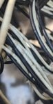
We observed the cables jaket broken in some cables, and not possible to replace the cables as a solution becuse the distance so far to marshaling in Control room.
I need a solution and how to prevent these spike signals.
Or if there another solution can implement it.
We have issue with the reading for RTD some times give spike signal and huntting that trip the motor , after trip the reading become normal and measeur the weather temperature.
Also the same happen for vibration sensors.
We observed the cables jaket broken in some cables, and not possible to replace the cables as a solution becuse the distance so far to marshaling in Control room.
I need a solution and how to prevent these spike signals.
Or if there another solution can implement it.
Attachments
-
 827.2 KB Views: 20