 Facebook
 Google
 GitHub
 Linkedin
DC Bus Fundamentals in Industrial Motor Drives
Learn about precharge circuits, inrush current, and understand why VFD and servo drives may trip during power-up.
When a VFD or servo drive won’t come ready, or it trips the instant power is applied, or it repeatedly faults during startup, the root cause is often in the drive’s front end—not inside the motor. Most power-up problems trace back to the rectifier, the DC link (DC bus), or the precharge circuit that charges the bus capacitors in a controlled way.
This is a practical, technician-friendly explanation of the DC bus, defining why inrush current is so punishing, how precharge works, what typical startup symptoms mean, and which measurements reduce troubleshooting time without increasing risk.
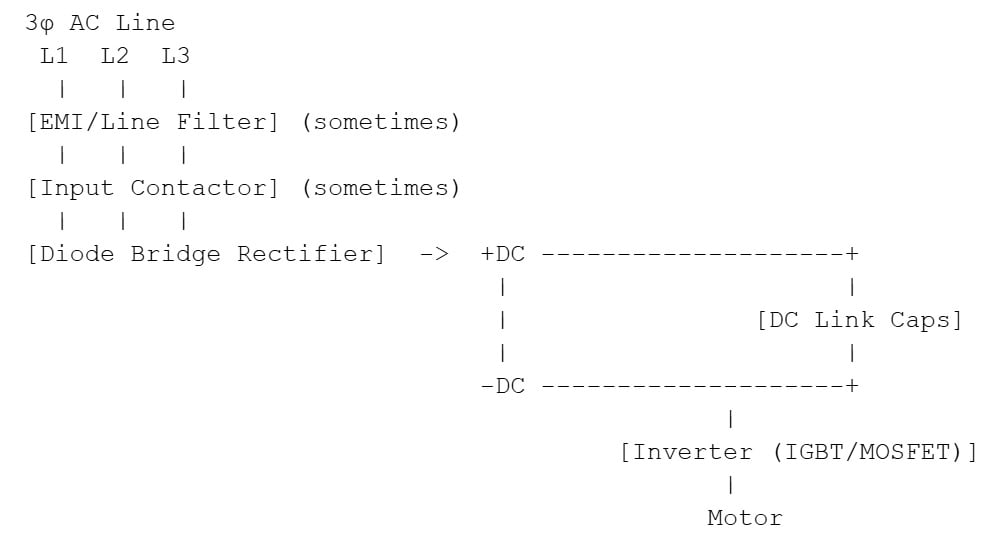
Figure 1. The drive front end at a glance. Image used courtesy of Wake Industrial
The rectifier converts incoming AC into DC. The DC link capacitors smooth that DC into a stable supply for the inverter, which synthesizes the variable-frequency/variable-voltage output to the motor. On many 480 VAC three-phase drives, a healthy, charged DC bus is commonly in the ~650–680 VDC range (exact values vary by topology and line conditions).
Why Does Inrush Current Happen?
At turn-on, the DC link capacitors are in their discharged state. Electrically, a discharged capacitor initially behaves like a short. The rectifier will try to charge the capacitor bank immediately, limited only by the system impedance (transformer, feeder, line filter, wiring, etc.). The resulting surge, or inrush current, can be large enough to open input fuses, trip upstream breakers, cause pitting on switching contacts, and stress the rectifier and bus components.
For a concise engineering overview of inrush behavior and limiting approaches, see Texas Instruments’ application note on inrush current limiting.
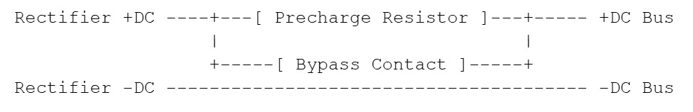
Figure 2. Precharge circuits: purpose and sequence. Image used courtesy of Wake Industrial
In normal startup operation, the bus voltage rises smoothly over a fraction of a second to a few seconds, limited by a precharge resistor. When the drive reaches a preset voltage threshold within a certain time, a bypass contactor/relay closes. Many drives make an audible click when this contact closes. If the drive never transitions to bypass, the bus may stall at a partial voltage or rise too slowly and trigger a timeout.
For practical context on capacitor behavior after extended storage (and why reforming is sometimes recommended), see ABB’s capacitor reforming instructions.
DC Bus Component Failures
Rectifier (diode bridge): A shorted diode or bridge assembly often produces immediate fuse opening at energization. An open or weak diode can allow the control section to power on while the bus never reaches the expected level, and it may increase ripple and heating.
DC link capacitors: Catastrophic capacitor failures can present as a hard short (instant fuse/breaker trip). Gradual degradation typically increases ESR and reduces effective capacitance, which can show up as nuisance undervoltage, unstable bus under load, or a charge timeout where the bus never reaches the threshold quickly enough during precharge.
Precharge resistor/bypass relay or contactor: An open precharge resistor, a bypass device that fails to pull in, or a sensing fault that prevents the bypass command are frequent causes of stuck charging, won’t enable, or repeated startup faults.

Figure 3. VFD failures should be identified rather than simply guessed. Image used courtesy of Adobe Stock
Interpreting Startup Symptoms Without Guessing
Learning to recognize failure symptoms can greatly accelerate the troubleshooting process.
Instant Fuse/Breaker Trip at Power-on
An immediate trip at energization strongly suggests a hard short in the front end. The most common offenders are shorted DC link capacitors or a shorted rectifier. Shorted surge suppression components (MOVs) can also cause instantaneous fuse opening. While an inverter short can sometimes reflect back as an input event, instant input fuse blow typically points to the rectifier/DC link first.
Charging Indefinitely or Never Becomes Ready
This pattern often implicates the precharge path. If the bus rises partially and stops, suspect an open precharge resistor or abnormal leakage. If the bus rises but the bypass never closes, suspect the bypass relay/contactor, its drive circuitry, or bus voltage sensing logic.
Undervoltage Faults During Power-up
Startup undervoltage can be a supply problem masquerading as a drive problem. Missing phase, imbalance, weak transformers, long feeders, or generator operation can all cause severe sag during capacitor charging. It can also occur when the precharge circuit is slow or inconsistent.
For an example of how DC bus undervoltage is typically described on a real industrial platform, see: Indramat F226 fault overview.
Overvoltage Faults on Power-up
Less common, but possible—particularly with high incoming line voltage, shared DC bus systems, or regenerative interactions. If the DC bus is influenced by other axes or a common supply module during startup, the bus can rise above limits before the drive’s control loop is fully active.
Safety first: DC buses can be lethal and can remain charged after power removal. Follow your lockout/tagout procedures, verify absence of voltage, and use appropriately rated meters and leads. Do not perform live bus measurements unless trained and authorized.
Verify the supply first. Measure L1-L2, L2-L3, and L1-L3 and compare. Significant imbalance or a missing phase can prevent normal bus charge and can also create misleading symptoms.
Observe the DC bus during the charging window (qualified personnel only). A healthy bus generally ramps smoothly. If it jumps then collapses, suspect a hard short or severe supply sag. If it creeps slowly and never reaches the threshold, suspect a precharge fault, excessive leakage, or degraded capacitors. If it reaches near-normal but won’t enable, focus on sensing/logic, the bypass device, or downstream enable conditions.
Resistance checks across DC+ to DC- (after verified discharge) can help identify a hard short. Interpret qualitatively—capacitors will often cause the meter reading to climb as they charge from the meter.
A Practical Troubleshooting Mindset
If the drive trips immediately at energization, assume a front-end short until proven otherwise: verify the supply, then evaluate rectifier/DC link integrity. If the drive powers its control electronics but never becomes ready, focus on whether the bus charging sequence completes and whether the bypass stage occurs. If the fault is undervoltage during power-up, validate the incoming supply under the actual charging event before condemning the drive. These steps align the symptom with the most likely subsystem and avoid unnecessary parts swapping.
Understanding the DC Bus
The DC bus is not mysterious—it’s a predictable energy reservoir with a predictable charging sequence. Once you understand the rectifier + DC link + precharge relationship, most startup failures fall into a few categories: hard shorts, incomplete/slow precharge, bus sensing issues, or plant-side voltage sag. Capturing what happens in the first two seconds after energization (instant trip vs delayed trip vs stuck charging) usually narrows the diagnosis dramatically.
Related Content


Hello,
The link you posted to “ABB’s capacitor reforming instructions.”
https://library.e.abb.com/public/1c0f84b7c70f4bd78d86a7c0e2ef2b8e/Capacitor_reforming_instructions.pdf
When trying to access the resource, you get an xml page which reads, in part:
“<Error>
NoSuchKey<Message>The specified key does not exist.</Message>...”
I know keeping up with bad links is a Sisyphean task, but it’s only been four days since you posted, so I think it was wrong from the beginning.
Please consider fixing this,
Thanks!