Facebook
 Google
 GitHub
 Linkedin
The Science of Mechanical Motion: Gears and Pulleys
The choice of load device and transmission method often dictates what kind of control system is used, so it’s important to be familiar with the mechanical and electrical components of a system.
Gear and pulley drive systems are, by far, the most common methods of moving mechanical energy from a source motor to a final load device. Almost everyone can recognize a belt and pulley drive system, since they are found under the hood of virtually every car and truck, plus countless other everyday devices. Gears are also very common, often hiding inside the casing of a gearbox or transmission. More importantly, they are also present in industrial machines.
Knowing the operating concepts (and the differences) of the two systems can help technicians choose the correct repair and maintenance methods, prevent future failures and ensure a long service life.
Gears: Rigid Mechanical Contact
Gear drives work well in three main scenarios: high precision is required, the motor is located very close to the load application, or a large change in speed and/or driving force is necessary.
Gears have an axle passing through them, providing an axis of revolution around which the rotation occurs. The relative alignment and distance between the two axes of revolution will dictate what type of gear is best suited for the application. If you imagine the two axes of revolution as infinitely long lines passing through the center of the gear along the axle, you should be able to determine their relationship.
The terms to keep in mind with gear alignment are offset and angle.
- The two axles may be located in parallel, but beside each other. This is called an offset misalignment.
- The two revolution axes may lie side-by-side like railroad tracks, but any variation is called an angle misalignment.
Note that misalignment does not mean the machine is broken; it's simply a reference to how lines and planes are related in 3D geometry.
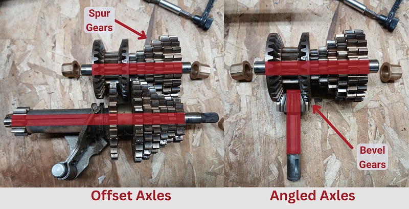
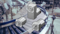
Figure 1. Spur gears to correct an offset (left side), and bevel gears to correct a 90-degree angle (right side). Image used courtesy of the author
For each type of misalignment, there are common gear choices seen in machines.
Same Angle, But With Offset
If two axles run parallel to each other, but side-by-side, a spur gear would be the most reasonable choice. This kind of gear is the simplest but most common gear type to encounter. The gear itself is a round disk with the teeth cut straight into the face along the outside edge.
No Offset, but With Different Angles
Many times, the motion transmission needs to change directions. If the angle is small, this can easily be accomplished with a universal joint or constant velocity (CV) joint. But if the motion must change 90 degrees, or if it must be transmitted from a single shaft into two output shafts, then the U-joint may not (or cannot) be suited for this task.
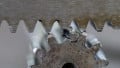
A bevel gear set allows this 90-degree alignment by meshing two gears, each with teeth cut into the outer edge of the 45-degree face. This allows the two 45-degree angles together to form a 90-degree angle change.
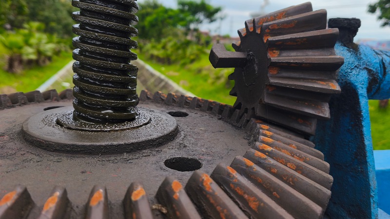
Figure 2. Bevel gears after manufacturing on a gear-cutting machine. Image used courtesy of Adobe Stock
Sometimes, a custom application may use different angles, such as a pair of 22.5-degree gears to form a 45-degree bend, but this is not nearly as common. One of the more recognizable appearances of bevel gears would be inside the differential of a rear-wheel-drive vehicle.
Different Angle, and With Offset
In some cases, the two shafts will pass directly over the top of each other at a 90-degree angle to each other. Two gear choices can meet this demand, one of them having a very particular benefit.
The simpler choice is two gears with much like spur gears, except the teeth are cut at 45 degrees across the outside face, and these are called helical gears. The teeth cut across the front face in either direction, providing the terms ‘left-hand’ and ‘right-hand’. If two like-handed gears are used together, the axes will be 90 degrees apart.
If a left and right-hand gear are used together, the shafts will be parallel, just like a spur gear. With the angled teeth, it can provide less noise and vibration since there is never a gap in the contact area.
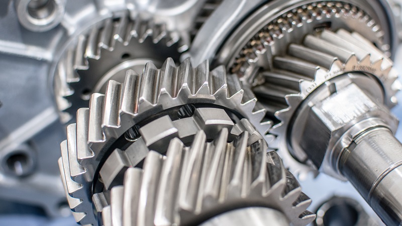
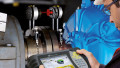
Figure 3. These transmission gears have a helix angle cut in order to provide lower noise and more constant force. Image used courtesy of Adobe Stock
The other type of gear for the offset-plus-angle misalignment scenario of 90-degree alignment is called the ‘worm gear' set.
One gear, the 'worm,' resembles a screw; it's basically one big gear tooth wrapped around a shaft. The worm is always the input shaft. The output is a helix cut gear with a slight angle in the teeth to match the worm gear profile.
The output shaft rotates much more slowly, but with a tremendous amount of rotational force. This is found in all sorts of cases when a high-speed motor is meant to drive a low-speed load device, but with much greater force.
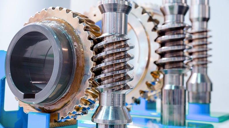
Figure 4. A worm gear set. Image used courtesy of Adobe Stock
Basic Overview of Pulleys
Pulleys with rubber belts are also very familiar, especially in vehicle systems. Nearly every car has a rubber v-belt or serpentine belt driving the pulleys in front of the engine.
For a belt system to run properly, the two (or more) pulleys should ideally be perfectly in line with each other, or in other words, the axes of revolution should be perfectly parallel. If not, the life of the belt is greatly reduced, and there will be more vibration.
Types of Belts
There are four major types of belts used for various scenarios:
V-belts have a trapezoid cross-section, and they sit inside a pulley with a V-shaped profile. The friction of the belt at high speeds allows motion transfer over a long distance. If one pulley becomes locked up, the motor may still rotate with the belt slipping. This isn't great news for the belt, but it can prevent a catastrophic motor failure.
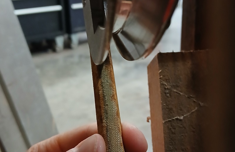
Figure 5. A v-belt being used. Image used courtesy of the author
Flat belts run on smooth, flat pulleys. They are often found driving multiple output shafts off of a single main input shaft. It used to be a staple of older steam-driven factories, long before the luxury of a separate motor at each point of motion.
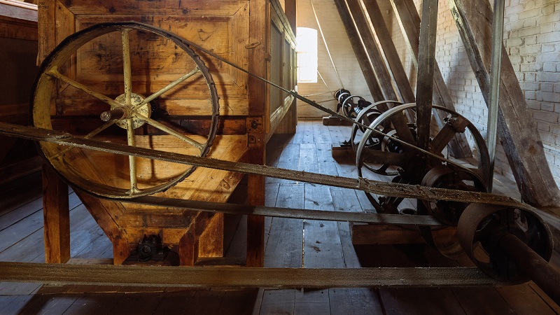
Figure 6. A restored factory with flat belts driven by a central axle. Image used courtesy of Adobe Stock
Serpentine belts have ribs running parallel to the length of the belt. The narrow profile makes them very flexible, allowing them to rotate around small pulleys. However, the surface area of the multiple ribs provides much more friction than a flat belt.
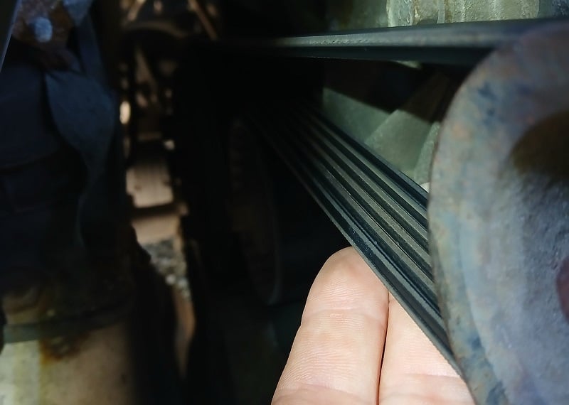
Figure 7. The flatter profile of a serpentine belt. Image used courtesy of the author
Timing belts are more like gears in the sense that they cannot allow the two pulleys to become disengaged from each other; no slipping is allowed if properly tightened. This is a great choice if two systems must rotate with a very precise relative speed, but they are too far apart to allow a complex gear train between them. Chain drive systems are worth mentioning along with timing belts. Chains can provide a similar precise matching of speed, but are well-suited for low-speed applications.
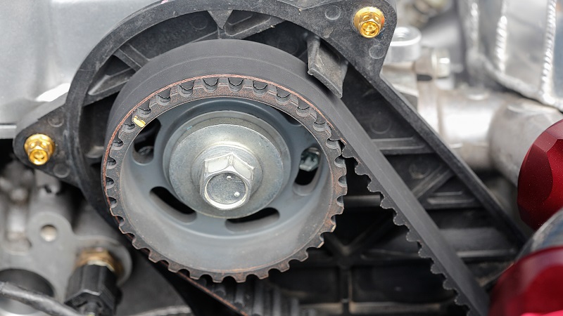
Figure 8. A timing belt with a matching sprocket. Image used courtesy of Adobe Stock
Importance of Mechanical Knowledge
Motion transmission is a complex subject. It’s very mechanical and easy to visualize, but the great diversity of component configurations can present their own benefits and challenges which are helpful for engineers and technicians to understand.
Revised: Original article published 9/2020