Facebook
 Google
 GitHub
 Linkedin
Fail‑Safe Motor Circuits: When Loss of Power Moves You Toward Safety
Part 1 of a 2-part series. A practical look at the failures that plague motor drive systems, even those that are rated to be fail-safe.
During commissioning of a small drain system, the motor starter logic “looked right” in the PLC. The pump showed STOPPED, the overload had not tripped, and the control screen claimed the pit was isolated. On a brief control‑power dip, though, the pump did not respond as expected; one phase of the contactor appeared to hang, the motor kept humming, and the level hardware behaved differently than the cause‑and‑effect chart suggested.
Variations of this story show up on sumps, dilution fans, and small isolation drives: documents say “fail‑safe,” yet in the event of a power loss or wiring fault, the motor does not reliably move into the intended safe state. The common thread is that de‑energized has been treated as automatically equivalent to safe, with normally open (NO) behavior assumed and normally closed (NC) behavior only considered for permissives or odds‑and‑ends.
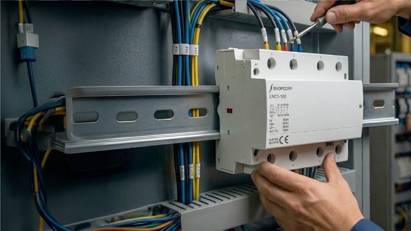
Figure 1. NC contactor assembly mounted on a DIN rail inside a motor‑control panel, used as part of an isolation or fail‑safe stage. Image used courtesy of Contactor Depot
This article is written for control and motor‑control engineers who specify contactors and write the logic around them. The goal is to use NC behavior—including NC auxiliaries, mirror‑contact concepts, and energize‑to‑trip arrangements—to move loads toward a defined safe state under credible faults, and to make welded contacts and feedback mismatches visible instead of mysterious.
For a broader overview of how normally open and normally closed contactors behave in standard control circuits, here is a general reference on NO vs NC contactors can help align terminology and expectations across the design team.
Normal vs Safe vs Fail‑Safe
In contactor terminology, the word “normal” refers to the mechanical state of the device with the coil de‑energized; sitting on the bench with no power applied. A normally open (NO) contact is open in that condition. It closes when the coil is energized. Therefore, a normally closed (NC) contact is closed at rest and opens when the coil is energized.
Functional‑safety literature, by contrast, often distinguishes energize‑to‑trip and de‑energize‑to‑trip functions. In a de‑energize‑to‑trip scheme, loss of power or internal failure causes the actuator to move toward the defined safe state by default. For many motor circuits, “safe” is “motor definitely unpowered,” but there are cases, such as drainage or ventilation, where safe means “allowed to run based on local conditions even if higher‑level control or communication disappears.”
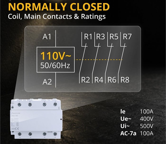
Figure 2. Simplified diagram of an NC contactor showing the coil terminals and four normally closed main poles (R1–R2, R3–R4, R5–R6, R7–R8) used for isolation or fail‑safe behavior. Image used courtesy of Contactor Depot
For practical design work, it helps to keep three ideas separate:
- Normal state: device at rest with coil de‑energized (NO contacts open, NC contacts closed).
- Safe state: condition of the load that reduces risk for people, equipment, and environment in a given hazard analysis.
- Fail‑safe behavior: overall circuit response in which loss of control power, open circuits, or certain internal faults cause the system to tend toward that safe state rather than away from it.
Once these are defined explicitly, the question of NO vs. NC becomes part of the safety reasoning, not just a drafting habit.
Why “Fail‑Safe” Motor Circuits Still Fail
Confusing De‑Energized With Safe
For a conventional starter, it is easy to assume that if the coil is off, the motor is off, and therefore, the system must be safe. That assumption ignores real‑world failure modes such as welded contacts, where arcing or mechanical damage fuses one or more poles so they no longer open when the coil drops out. In that case, the PLC may show STOP while the motor remains energized or partially energized.
Choosing NO by Catalog Default
Most power contactors sold for motor starters have NO main poles as the standard configuration, with auxiliary blocks providing combinations of NO and NC contact points. This leads many designs to default to energize‑to‑run, de‑energize‑to‑stop behavior, whether or not that is appropriate for the safe state.
Where a de‑energize‑to‑trip behavior is desired, designers often need to build it using standard NO power contactors wired so that energizing the coil opens the circuit (energize‑to‑open), or by using dedicated safety contactors and shunt‑trip devices whose operating principles are documented in the safety scheme. If the drawings only show a “NC contactor” symbol without explaining this, a reader may reasonably expect to find a pure NC power contactor in the catalog and be confused when it does not exist in that form.
Leaving Fault States Underspecified
A specification might say “pump stops on fault” without elaborating what happens under the following conditions:
- Loss of 24 V control power to the starter.
- Open circuit between the PLC output and the coil.
- Internal coil failure (open, short, or partial short).
Without a simple state table, each person involved may picture a different behavior in these fault cases, and the final panel may not match any of those mental models.
Underestimating Welded Contacts and Feedback Integrity
Contact welding is a well‑known failure mode in relays and contactors, typically caused by arcing at make or break, especially under fault or overload conditions. In many panels, auxiliary contacts are used opportunistically, perhaps one spare NO for a pilot light, one NC in a permissive chain, all without a strategy for detecting when the main power path is stuck closed.
Mechanically linked and mirror‑contact concepts exist precisely to improve this situation. Mirror contacts are NC auxiliaries mechanically arranged so that they cannot be closed at the same time as the associated main NO contacts; if a main pole welds, the mirror contact will not indicate a false “safe” state. Without some form of trustworthy feedback, logic that assumes “coil off = open” can be badly misled.
Uncovering the Solutions
Now that the problems are defined, be sure to read the next article, in which we will explore a few rational strategies that can bring a stronger state of safety to the control system.
Related Content