Facebook
 Google
 GitHub
 Linkedin
Applying Fail-Safe Solutions to Protect Motor Control Systems
Part 2 of a 2-part series. A practical look at how normally closed (NC) power contacts and feedback can drive loads toward a defined safe state under real‑world faults.
Previously, an article addressed the problems that can face fail-safe motor starting circuits. In this follow-up article, we’ll examine some of the strategies that bring a stronger sense of safety with normally closed (NC) contacts and feedback.
A proper solution requires a complete change in mindset regarding controls, as evidenced by four distinct patterns of behavior.
Pattern A: Safe State First, Hardware Second
A practical way to start is to write down, load by load: “If everything goes wrong and control power disappears, what state of this motor is actually safer?” For a conveyor feeding a shredder, the safe state is almost always unpowered, possibly with a defined deceleration path. For a sump pump preventing flooding, the safe state might be “allowed to run whenever local level calls for it,” even if the supervisory PLC is offline.
Once the safe state is clear, you can answer two questions:
- Should energizing the coil apply power (standard NO starter) or remove power (energize‑to‑open or shunt‑trip)?
- Should NC auxiliaries be used so that broken wires and loss of permissive power cause the system to move toward safe?
This framing keeps discussions about NO vs NC grounded in hazard analysis instead of catalog defaults.

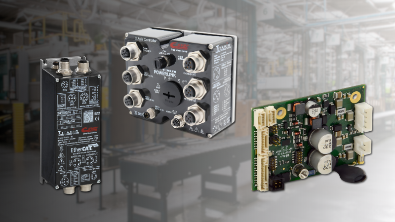
Figure 1. Form factors of standard motor contactors. Image used courtesy of Contactor Depot
Pattern B: Using NC Behavior to Move Toward Safe
Because pure NC power contactors are uncommon in many catalogs, NC behavior in motor circuits is often implemented using standard NO contactors wired in energize‑to‑open configurations or in series with other devices. Two patterns show up frequently:
- Energize‑to‑run with NC permissives. The main starter remains NO, but crucial interlocks (such as guard doors, emergency stops, or over‑temperature trips) are implemented with NC contacts in series with the coil. A broken wire or loss of power to the interlock device opens the path and prevents the motor from running, pushing the system toward a de‑energized safe state under those faults.
- Energize‑to‑open isolation. A standard NO contactor or safety contactor is placed upstream as an isolation device. Its coil is energized only when a safety function demands isolation; otherwise it remains de‑energized and closed, allowing the local control (such as a float switch) to manage the load. In a control‑power loss, the isolation coil de‑energizes and the device relaxes to its normal state, which should be chosen to match the defined safe state for that application.
If you are selecting hardware for this kind of behavior, reviewing a catalog view of normally closed contactor configurations and related accessories can clarify what combinations of poles and auxiliary contacts are actually available in common frame sizes.
In both patterns, NC behavior essentially comes from how standard components are arranged, not from assuming that NC power contactors are as ubiquitous as NO starters.
Pattern C: Feedback Integrity and Mirror Contacts
Feedback integrity means that status signals used in logic genuinely reflect the state of the power path. Basic practices include:
- Using dedicated auxiliary points for “contactor closed” and “contactor open” status instead of assuming the command output tells the whole story.
- Where available, using mechanically linked or mirror‑type auxiliaries whose geometry prevents them from indicating “safe” when a main NO contact is welded closed.
- Implementing simple mismatch detection: if the logic commands a transition and the corresponding feedback does not follow within a timeout, the system declares a fault and inhibits further automatic attempts.
Manufacturers’ notes on mechanically linked and mirror contacts highlight that these features are intended to support fault detection and safety functions, but they do not by themselves make a system compliant with any specific standard; the overall architecture and verification still matter.
Pattern D: Treat Welded Contacts as Inevitable
Instead of treating welded contacts as “unlikely,” it is better to assume they will happen occasionally over the life of a system and design the control logic accordingly. Common detection cues include:
Failure to transition: command is OFF, but “closed” feedback stays true.
Contradictory feedback: current or speed indicates running while the PLC believes the starter is open.
Mirror‑contact refusal: a mirror‑type auxiliary never indicates “safe” even though the coil has been de‑energized.
When such a mismatch is latched, the response should be:
- Inhibit automatic restarts.
- Annunciate clearly that a welded or hung contact is suspected.
- Require a maintenance intervention that includes actual measurement at the device rather than just cycling the coil command.
State Table 1: Normal, Fault, and Power‑Loss Behavior
State tables help capture how a starter is expected to behave across normal and fault conditions. The example below describes a starter where the safe state is “motor de‑energized,” using an NO main contactor with NC permissives and aux feedback.
| Scenario | Run command | Coil state | Main contact state (intended) | Motor state | Feedback state (intended) |
| Normal stop | OFF | De‑energized | Open | Stopped | “Open” feedback made, “closed” feedback clear |
| Normal run | ON | Energized | Closed | Running | “Closed” feedback made, “open” feedback clear |
| Loss of control power | (Don’t care) | De‑energized | Open via NC permissives | Stopped (safe) | “Open” feedback made or input power lost |
| Broken wire in permissive path | ON | De‑energized | Open | Stopped | “Open” feedback made, fault bit set in PLC |
| Coil failure (open circuit) | ON | De‑energized | Open | Stopped | “Open” feedback made, “failed to energize” alarm |
In a design where “safe” means the same as “allowed to run,” the table would be adjusted so that loss of control power does not block local control or essential functions but still provides a visible indication that supervisory control is unavailable.
State Table 2: Welded‑Contact Scenarios
A separate table focused on welded contacts clarifies how the system should react when main poles do not open as expected.
| Scenario | Command | Coil state | Actual main contacts | Aux / mirror feedback | Mismatch / risk | Recommended response |
| OFF command, welded pole, standard aux | OFF | De‑energized | One pole remains closed | Standard aux shows “open” | Motor may still be energized; feedback lies | Require periodic test cycles; rely on current/voltage checks |
| OFF command, welded pole, mirror aux | OFF | De‑energized | One pole remains closed | Mirror aux does not show “safe” | Safety logic refuses to reset | Treat as fault; lock out until device is inspected |
| Power loss, welded pole | (N/A) | De‑energized | Welded pole remains closed | Feedback depends on design | “Safe on power loss” assumption may be invalid | Require absence‑of‑voltage test before working on circuit |
Using mirror‑type feedback in the second row does not remove the weld, but it helps prevent a dangerous combination of “main welded” and “feedback claims safe.”
Using NC‑Oriented Hardware Deliberately
In practice, NC behavior is implemented with combinations of devices rather than relying on pure NC power contactors as a standard catalog item. That can include NO starters controlled in energize‑to‑open schemes, safety contactors with forcibly guided contacts, and upstream isolation stages that open when a safety relay energizes them.
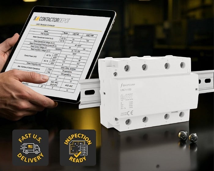
Figure 2. Example of a four‑pole NC contactor with its specification sheet, including current ratings, utilization categories, and applicable IEC/CE standards. Image used courtesy of Contactor Depot
If you are evaluating concrete hardware options, a product example of a multi‑pole, normally closed IEC contactor assembly illustrates how NC poles are packaged and rated for mixed motor and lighting loads, including HVAC‑type applications, when used as part of a de‑energize‑to‑trip isolation stage rather than as a conventional motor starter.
In design reviews, it helps to annotate schematics with functional names for commands, feedback, and weld‑fault indicators instead of leaving everything as generic “Aux 1” or “Aux 2.” That small step keeps drawings, PLC tags, and terminal markings aligned and makes later modifications less error‑prone.
Design Checklist (Short and Actionable)
- Define the safe state of each motor or load in plain language, including what happens during loss of control power and why that state is safer.
- For each fault type (loss of control power, broken control wire, coil failure, welded contacts), document what actually happens to the load and whether that still matches the safe state.
- Decide where NO vs NC behavior is required: standard NO starters, energize‑to‑open isolation, NC auxiliaries in permissives, and any mirror‑type feedback needed for fault detection.
- Specify what evidence confirms that contactors really opened or closed: auxiliary feedback, mirror contacts, current/voltage sensing, or a combination.
- Define how welded contacts and feedback mismatches are detected and what interlocks and alarms should do when they are suspected.
- Capture these assumptions in schematics and PLC naming (for example, separating command tags from feedback tags and weld‑fault tags) so later readers understand the intent.
Commissioning and Verification Steps
Before declaring a motor circuit “fail‑safe,” it should be exercised against the intended behavior:
Continuity and polarity checks: With coils de‑energized, verify that NO and NC contacts (both power and auxiliary) match their symbols and device markings.
Mechanism exercise: Energize and de‑energize each contactor while monitoring both main poles and auxiliaries; confirm that transitions match the state tables, within expected timing tolerances.
Feedback mapping: In the PLC or safety relay, verify that each feedback point changes exactly when the associated contact moves, not merely when the command output toggles.
Mismatch simulation: In a safe test environment, simulate stuck feedback or missing transitions (via forces, jumper removal, or test inputs) and confirm that logic sets and latches the correct fault bits and inhibits automatic restarts.
Power‑loss testing: Remove control power and observe the resulting state of each motor and isolation device. Confirm that the behavior matches the documented safe state and that automatic restart does not occur unexpectedly when power returns.
Safety Patterns and Tools
The patterns and steps explained in this article help an engineer convert the state table scenarios from design artifacts into observable behavior that can be verified during FAT, SAT, and later, maintenance. Using tools like these can ensure that safety is designed into circuits from the very beginning, and never left as an opportunistic afterthought.