 Facebook
 Google
 GitHub
 Linkedin
Using 2NO/2NC Contacts to Make Motor Starters More Fail‑Safe
A practical look at how 2NO/2NC contactors and auxiliary contacts can clean up command, feedback, and fault logic in motor circuits.
During startup of a new conveyor line, the forward/reverse starter “looked fine” on paper. The PLC issued a forward command, the RUN light came on, and the HMI said the motor was healthy. On the floor, however, the drum never moved. The contactor coil sounded like it tried to pull in, the overload sat untouched, and the electrician was left chasing a problem that shouldn’t have passed FAT.
You see the same failure pattern on overhead cranes, HVAC condenser fans, and small packaging conveyors: status points claim RUN while the motor is parked, or an interlock that “should” be there quietly fails. The details change, but the core issue repeats wherever simple starters and forward/reverse contactors are used.
This article is written for control and automation engineers who design FWD/REV starters or HVAC motor starters and then have to support them during commissioning and service.
The focus is on using 2NO/2NC auxiliary contact blocks intentionally so that command, status feedback, and fault monitoring are clearly separated.
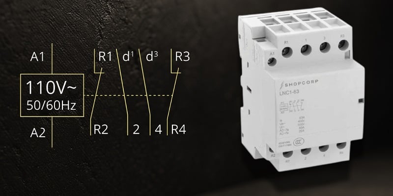
Figure 1. DIN‑rail 4‑pole (2NO/2NC) contactor device and schematic. Image used courtesy of Contactor Depot
The Problem of Unknown States
Many motor control issues boil down to ambiguous states. The coil might be commanded on, but you don’t actually know if the main contacts have closed, if the mechanism has latched, or if a welded contact is hiding behind a “normal” status.
In many panels, auxiliary contacts are used simply because they were there. A spare NO feeds a RUN pilot light, an NC sneaks into a permissive chain, and the same contact might try to serve as both seal‑in and status. Nobody writes down which signal represents command, which represents actual contact movement, and which is intended for interlocking.
The result is familiar on the floor: RUN indicators that mirror the coil command instead of the contact position, interlocks that depend on the wrong contact, and PLC tags labeled “ContactorIn” that actually mean “CoilCommand.” Nothing is technically shortened or open where it shouldn’t be, but the system doesn’t tell a clean story when something goes wrong.
Why Ambiguity Happens
When the coil energizes, the armature should move. Both the main and auxiliary contacts change state: the normally open contacts close and the normally closed contacts open according to the device design. Electrically, that motion should represent a clean transition from no motor power to power applied, and in terms of indicators, from STOP to RUN.
In practice, drawings drift away from actual wiring, spare contacts get repurposed during commissioning, and the functional meaning of each NO/NC contact is never captured in one place. Without a shared definition of states, a simple forward/reverse starter becomes hard to reason about under fault.
For a deeper dive into general auxiliary contact behavior, an auxiliary contact reference can help align terminology and expectations across the design team.
A Better Approach
Instead, we can treat a 2NO/2NC auxiliary block as four distinct tools, each with a defined job, instead of a pile of spare contacts. This arrangement provides two NO and two NC contacts mechanically linked to the same coil movement, which is usually enough to separate command, feedback, and interlock functions in a motor starter.
One practical assignment for those four contacts is:
- One NO for seal‑in: holding the coil once it pulls in.
- One NO for pick‑up feedback: RUN status back to a pilot light or PLC input.
- One NC for reversing interlock: in series with the opposing coil.
- One NC for drop‑out feedback: confirming the contactor has actually opened when commanded off.
Electrical interlocking in a forward/reverse set is typically implemented by wiring the NC aux contact from the one starter in series with the opposite coil, and the NC from the reverse starter in series with the forward coil. That way, if FWD is picked up, FWD_INTERLOCK_REV opens and prevents the REV coil from energizing. A mechanical interlock between the two contactors remains a separate safeguard: it physically prevents both from closing at once even if someone miswires the electrical interlock.
The last piece is a simple state table or truth table that defines what each combination of command and feedback signals should look like in normal operation and in common fault conditions. Instead of hoping the ladder “looks right,” you now have a small spec that the wiring, PLC logic, and commissioning tests all point back to.
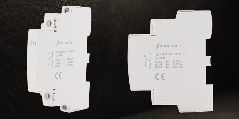
Figure 2. Two clip‑on auxiliary contact blocks with NO/NC terminal markings, providing additional feedback signal points. Image used courtesy of Contactor Depot
Working Example: Forward/Reverse Starter
Consider a standard forward/reverse starter with two contactors: FWD and REV. Each contactor has a 2NO/2NC auxiliary block or separate clip‑on auxiliary modules. We will focus on the forward side, with names kept consistent between text, table, and logic.
Signal Naming and Roles
For the forward starter, define these signals:
- FWD_CMD: Command to the FWD coil (from pushbutton circuit or PLC output).
- FWD_RUN_FB: NO auxiliary feedback; closes when the FWD contactor mechanism has actually moved.
- FWD_DROP_FB: NC auxiliary feedback; closed when the FWD contactor drops out and opens when it pulls in.
Simplified State Table
Here is a compact state table for the forward starter, using those signal names:
| State description | FWD_CMD | FWD_RUN_FB | FWD_DROP_FB | Description |
| Stopped | OFF | OPEN | CLOSED | Normal STOP state |
| Forward run | ON | CLOSED | OPEN | Normal RUN state |
| Command ON, RUN feedback OFF | ON | OPEN | CLOSED | Command/feedback mismatch |
| Command OFF, RUN feedback ON | OFF | CLOSED | EITHER STATE | False RUN / possible weld or jam |
| Command OFF, both feedback OFF | OFF | OPEN | OPEN | Wiring/selection error on DROP_FB |
Contact bounce and mechanical timing differences during pick‑up and drop‑out still exist, but those are transient and don’t need their own rows. In practice, short PLC on‑delay or off‑delay timers on FWD_RUN_FB and FWD_DROP_FB are enough to ignore millisecond‑scale chatter while still detecting real mismatches.
Interpreting the Abnormal States
- Command/feedback mismatch – FWD_CMD ON, FWD_RUN_FB OPEN, FWD_DROP_FB CLOSED.
The PLC should treat this as “command present, no movement.” Typical actions: time‑limit it and generate an alarm such as “FWD contactor failed to pick up,” and the technician should verify coil voltage, upstream permissives, and mechanical free movement of the contactor.
- False RUN – FWD_CMD OFF, FWD_RUN_FB CLOSED.
Here the PLC is seeing a false RUN. It should inhibit a reverse start and flag a “FWD contactor feedback stuck” condition. In the field, the technician should meter the main contacts and the auxiliary block to check for a welded aux or a hung mechanism.
- Wiring/selection error – FWD_CMD OFF, both feedback signals OPEN.
This suggests the supposed NC drop‑out feedback contact was wired as NO or not wired at all. The PLC should mark FWD_DROP_FB as unreliable, and the technician should trace the wiring and confirm that the chosen contact actually closes when the starter is dropped out.
Even with this structure, a single auxiliary cannot guarantee detection of every welded contact scenario. The goal is to make the most common mismatches obvious, so you aren’t blind to a stuck RUN feedback or a failed coil.
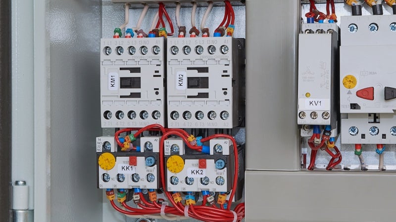
Figure 3. Some contactors include aux contacts, while others require add-on blocks. Image used courtesy of Adobe Stock
Using 2NO/2NC Deliberately
If you are selecting hardware, reviewing an example 2NO/2NC contactor configuration can clarify what contact combinations are available and how the poles are grouped, especially for compact contactors used in HVAC and light industrial panels.
In design reviews, annotate the schematic with the functional names (FWD_RUN_FB, FWD_DROP_FB, FWD_INTERLOCK_REV, etc.) instead of leaving everything as generic “Aux 1” or “Aux 2.” That small step keeps drawings, PLC tags, and terminal markings aligned and makes later modifications less error‑prone.
Pre‑Commissioning Verification Checklist
Before you energize a new motor starter, a short check can save a lot of time later:
- Bench‑check “normal”: With the coil de‑energized, verify NO and NC auxiliaries are indeed open and closed, respectively, with a meter.
- Exercise the mechanism: Manually operate the contactor (if possible) and confirm each auxiliary contact changes state as expected.
- Verify electrical interlocks: With FWD held in, confirm FWD_INTERLOCK_REV actually opens the path to the REV coil, and mirror that test in reverse.
- Confirm roles: Identify which NO is used for seal‑in and which for FWD_RUN_FB; identify the NC used as FWD_DROP_FB. Make sure no single contact is doing double duty.
- Build the state table: Record all states using FWD_CMD, FWD_RUN_FB, and FWD_DROP_FB, and keep that one‑page table with the project documents.
Troubleshooting Patterns
When something misbehaves in the field, having clear signal names and a simple state table turns troubleshooting into pattern‑matching instead of guesswork.
- Symptoms: RUN light on, motor stopped
Likely causes: RUN indicator wired to FWD_CMD instead of FWD_RUN_FB; welded RUN auxiliary; failed coil with command still present.
What to test: Meter the main contacts and FWD_RUN_FB; if FWD_RUN_FB is closed but the main contacts are open, suspect the auxiliary block or mechanism. - Symptoms: Forward/reverse interlock fails “occasionally”
Likely causes: FWD_INTERLOCK_REV wired to the wrong NC contact; documentation reversed NO/NC terminals; loose wiring on the interlock path.
What to test: With FWD energized, check that continuity in the REV coil circuit is truly broken by FWD_INTERLOCK_REV; repeat with REV energized, watching the forward coil path. - Symptoms: PLC shows both FWD_RUN_FB and REV_RUN_FB true at once
Likely causes: Both feedback inputs taken from coil commands; feedback contacts tied to a common source instead of their specific starter.
What to test: Run only FWD and meter both feedback inputs; REV_RUN_FB should be clearly open. If it isn’t, trace where the two feedback paths join. - Symptoms: Starter stops, but FWD_DROP_FB never confirms
Likely causes: FWD_DROP_FB wired to the wrong contact; NC contact failed open; input not actually landed on the PLC terminal.
What to test: De‑energize FWD and verify that the chosen NC contact closes; if the PLC input doesn’t see that change, look for broken conductors or mis‑landed wires between the terminal block and the input card.
Each of these patterns maps back to one or two rows in the state table, so the technician can quickly decide whether to suspect the coil circuit, the aux block, or the way those signals are interpreted in logic.
Summary
The use of 2NO/2NC auxiliary blocks provides four defined tools, and they should not be treated as generic spare contacts. A brief state table can preserve the initial designations of signals like FWD_CMD, FWD_RUN_FB, and FWD_DROP_FB that cover healthy STOP/RUN and a few key mismatch conditions.
Applied consistently with 2NO/2NC contactors in HVAC and small industrial motor applications, this pattern reduces false RUN indications and speeds up FAT and commissioning, both on the panel and in the field.


Nice article. I would add that that’s why many contactors comply with the mirror contact function, when both NO-NC contacts are open, is (certified) sign that at least one contact is likely welded. Very usefull to chenck in evry opening and trigger safety if isolation is at risk.