 Facebook
 Google
 GitHub
 Linkedin
VFD-Induced Bearing Currents: Six Checks for Controls Engineers
While mechanical wear in rotating machinery may be obvious over time, electrical faults can also cause bearings to fail. Unfortunately, the symptoms can look surprisingly similar.
A pump or fan motor may run normally for months after a VFD retrofit, and then suddenly, a vibration alarm prompts a bearing replacement. The first maintenance request may focus on grease, alignment, or bearing fit. Those are legitimate checks, but they may miss an electrical cause that was actually the original culprit of the failure.
For a controls engineer, the question is not always mechanical; it’s whether the drive, motor, cabling, grounding, and driven machine provide a path for electrical current. The answer often lies in details shared between electrical commissioning and mechanical maintenance. We must answer this question before simply discarding a failed bearing.
How Does a VFD Electrify a Bearing?
A PWM inverter (which is the operation inside a VFD) rapidly switches its output to control motor voltage and frequency. These fast transitions can produce high-frequency shaft voltage and bearing current even when the motor is not subject to direct winding insulation problems.
There are three different mechanisms at play:
1. Capacitive discharge current. Common-mode voltage couples through internal motor capacitances and can charge the shaft to a higher voltage than the frame. If the voltage exceeds the bearing's insulating capability, a brief discharge (arc) passes through the rolling contact. These arcs produce electrical-discharge-machining (EDM) pits.
2. High-frequency circulating (eddy) current. In some motors, common-mode current in the stator creates high-frequency magnetic flux that induces voltage between shaft ends. Current can then circulate through the shaft, bearings, and motor frame. This mechanism is more common in larger motors.
3. Shaft-grounding current. High-frequency voltage differences between the motor frame, shaft, and connected equipment can drive current through a motor bearing and along the shaft and coupling to ground. Bearings in a connected gearbox or pump may also become part of the return path.
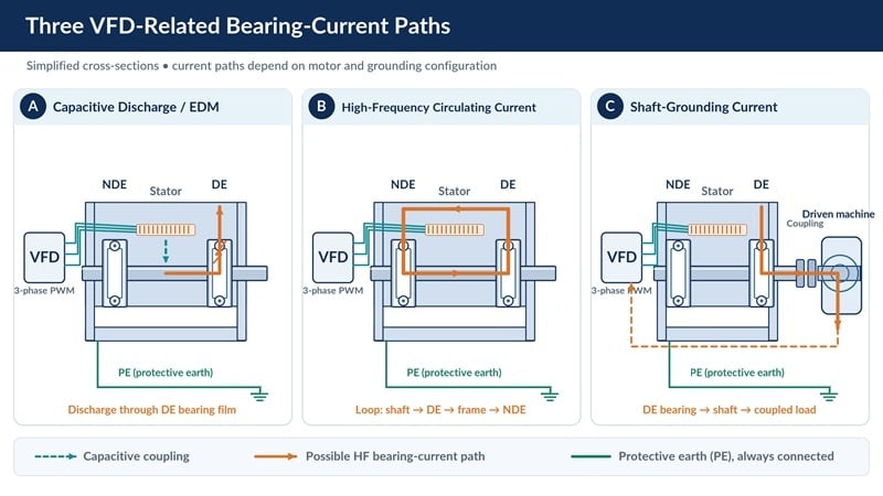
Figure 1. Simplified conceptual examples of three bearing-current mechanisms. Image used courtesy of TFL Bearings
What Can the Failed Bearing Teach You?
Since the arc path jumps from the races to the bearing rollers, this electrical erosion often leaves a dull or frosted surface appearance on the raceway. There may be small visible or microscopic craters, or regularly spaced ridges known as fluting.
There is a critical distinction to make: neither dark grease nor a vibration alarm establishes an EDM diagnosis on their own. Lubricants may deteriorate, and some gray surface markings can have non-electrical causes, including abrasive contamination.
| Observation during inspection | Possible electrical interpretation | Alternative explanation to check |
| Frosted raceway or fine pitting | Repeated electrical discharge | Abrasive contamination, corrosion, or other surface damage |
| Regular washboard-like fluting | Progressive electrical erosion | Other periodic wear or indentation patterns; examine morphology and location |
| Darkened or degraded grease | Current-related lubricant deterioration | Overheating, oxidation, contamination, or incorrect lubricant |
| Failure following a VFD or cable change | An altered high-frequency current path | Changed duty cycle, load, alignment, or maintenance conditions |
Photograph the raceways before cleaning and use magnification when necessary. Compare the pattern with the operating history. Motor noise, discoloration, or grease condition alone cannot confirm electrical erosion.
Six Checks Before the Next Bearing Replacement
The steps presented below are intended as a deeper investigation that bridges controls and maintenance. This process is not meant to be a substitute for the manufacturer's procedures, but rather an additional layer that may help prevent future problems.
1. Preserve Evidence Exposed at Removal
Before cleaning or disposing of the failed bearing, take pictures of the inner and outer raceways, rolling elements, seals, and grease. Record the complete bearing designation and which motor end it came from: drive end (DE) or non-drive end (NDE). Save any vibration trend data, operating history, and recent drive changes.
On the electrical side, capture the VFD model, carrier-frequency setting, speed and motion profiles, and the cable type and approximate length. These details might be hard to reconstruct after a shutdown.
2. Investigate Both Electrical and Mechanical Causes
Before ruling out mechanical issues, be sure to check lubrication, contamination, bearing fit, shaft and housing condition, alignment, loading, and damage position relative to the load zone. Electrical erosion and mechanical damage can coexist. If a replacement bearing fails repeatedly, compare the failure pattern with the prior teardown rather than assuming that the same symptom always has the same cause.
3. Inspect Earth and Shield Bonding
Review the actual return path from the motor to the drive, including protective earth (PE) conductors and the motor-cable shield. Are shield terminations and bonding connections installed according to the drive manufacturer's instructions? Where specified, inspect 360-degree shield termination at both the drive and motor ends. Look for long pigtails, corroded joints, painted contact surfaces, or connections changed during an outage.
Remember that impedance changes with VFD-related high frequencies, so a satisfactory DC continuity test only verifies a conductive connection. Protective earthing must remain compliant with applicable electrical-safety requirements, especially while in operation.
4. Compare the Installed Configuration With the Intended Design
Verify the cable construction, routing, approximate length, shield or armor termination, and any output filtering. Also check whether the carrier frequency was changed after commissioning, perhaps to reduce audible motor noise.
Distinguish the purpose of each device. Load reactors and dV/dt filters are commonly applied to reduce motor-terminal voltage stress and switching-related overshoot; their bearing-current effects depend on design. Common-mode filtering addresses the high-frequency common-mode return path more directly. Check the manufacturer's filter specifications rather than assuming any output filter will suppress bearing currents.
The U.S. Department of Energy discusses reducing carrier frequency to 2–5 kHz as one mitigation measure. This is guidance, not a universal setting. Any change must remain within the drive and motor manufacturers' limits, including thermal, acoustic, and control-performance considerations.
5. Arrange an Appropriate Measurement
A traditional ammeter or clampmeter intended for 50/60 Hz measurements cannot characterize fast voltage transients or bearing-current pulses. Where justified, use a suitable shaft-voltage measurement arrangement and manufacturer-approved procedures to examine the waveform under normal operating conditions.
Be sure to use the site's approved electrical-safety and guarding procedures; do not improvise a probe arrangement on a running shaft. Interpret any shaft-voltage trace alongside bearing damage and the complete current path. One voltage reading, without its waveform and measurement context, is not a universal pass/fail result.
6. Match the Solution to the Identified Mechanism
If the inspection finds poor high-frequency bonding or an unsuitable cable installation, correct those issues in accordance with the equipment manufacturer's requirements. Further measures may include revised drive settings, appropriate common-mode filtering, a shaft-grounding device, or an electrically insulated bearing arrangement.
Coated-ring insulated bearings use a layer of insulation on the inner or outer mounting surface. Hybrid bearings use ceramic rolling elements between steel rings. Both approaches restrict current and arcing, but their capacitance and high-frequency impedance are different. The choice requires consideration of bearing location, shaft grounding, drive conditions, and the coupled machine.
Also examine the gearbox, pump, or other coupled equipment. Reducing current through the motor bearings must not unintentionally leave another component as the preferred path to ground.
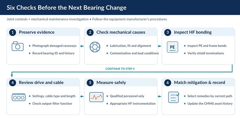
Figure 2. A practical sequence for controls and maintenance teams. Image used courtesy of TFL Bearings
Record the Findings!
The work is not complete when the new bearing is installed. Add an appropriate VFD–bearing configuration note that captures important details in the computerized maintenance management system (CMMS) or asset history.
• Drive and motor: asset IDs, VFD model, carrier-frequency setting, and normal operating speed range.
• Installation: approximate motor cable length, cable type, shield termination, high-frequency bonding, and installed filters.
• Bearing arrangement: complete designations, drive-end (DE) and non-drive-end (NDE) positions, and any shaft-grounding device.
• Evidence and action: raceway photos, relevant waveform captures, repair findings, mitigation implemented, and dates.
• Future ownership: who approves drive-parameter changes and who confirms bearing substitutions during repairs.
Retrofits are one of the primary reasons why this record should be maintained. A future technician might change a drive setting without knowing why a shaft-grounding ring was fitted, or substitute a standard NDE bearing with identical dimensions. The record preserves the original reason for the protection arrangement.
Practical Lessons
An early bearing failure on a VFD-driven motor always deserves both the mechanical inspection and the electrical installation review. It’s not good enough to simply chase down a solution based on the appearance of the damaged bearing. Always remember to preserve evidence, identify the plausible current path, and choose the corrective measure for that mechanism.
Related Content