Configuring a Network With Pneumatic Valve Manifolds
There are many distributed fieldbus capabilities for valve manifolds that can save on network overhead and wiring. In this article, we will look at PLC programming of fieldbus manifolds highlighting Festo's CPX layout.

Figure 1. Manifolds are necessary for compressed air systems that use pneumatic devices. Image courtesy of Festo
Valve Manifold
Any compressed air system that makes use of multiple pneumatic devices, such as actuators or linear slides, requires the use of a manifold. Pneumatic manifolds consist of a series of pneumatic valves grouped and all sharing the same compressed air supply, but with individual solenoid controls for each valve.
When a particular valve is energized to change positions or spool to position two, the air supply is directed to another port, only for that particular valve. All of the pneumatic devices within the system are connected pneumatically to the manifold. This style of pneumatic design reduces wiring and pneumatic hose installation and helps with troubleshooting programming and electrical issues.
Fieldbus vs Wired Manifolds
Before the inception of fieldbus protocols, each valve would have to be wired back to physical outputs on the PLC. This practice can be seen often on legacy equipment, and even on occasional new installations. The valve bank would have a large electrical connector with a large multi-conductor cable that would run back to the electrical cabinet. This style was very time consuming for electricians, and when outputs failed, the electrician would then need to move to a different output terminal address and change the program.
Today, most valve banks have the option for industrial communication protocols. By having the valve bank on the industrial network, complex wiring is virtually eliminated. The valve bank simply requires DC power and a network connection.

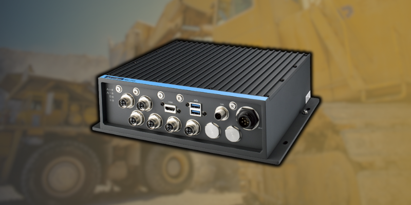
Figure 2. Festo CPX demonstration using distributed Ethernet/IP and Modbus TCP for valve terminals and I/Os from Automate 2022. Image supplied by Control.com
PLC Programming of Fieldbus Manifolds
Once the PLC has access to the valve bank through the industrial network, the valves can be triggered through toggling bits within the network memory map, which would likely appear as a 16 or 32-bit integer tag. The data size of each valve bank tag will depend on how many valves are installed within the manifold.
To make troubleshooting easier and simplify the readability of the PLC code, it is common practice to give the valve bank in the network tree a name that reflects its location within the machine. For example, you could name it VBRobot1 or VBCell2. With the valve bank named, you can now copy blocks of memory into a user-defined data type that accurately describes the function of each valve, such as Rob1GripOpen or EscapExt (escapement extend).
Sensor Inputs and Valve Outputs
When using pneumatic actuators, you will typically encounter sensors mounted on the actuator to determine the extend and retract positions. These sensors would normally have to be wired back to PLC input terminals in the electrical cabinet. Today, most manufacturers have inputs built into the valve bank and registered on the industrial network memory map. This means when you add your valve bank to your network tree, you will have access to outputs (the valves) and inputs (the sensors on the actuators).
In the PLC code, the inputs will be handled in much the same fashion as the outputs. Depending on how many inputs are installed in the valve bank, the size of the data integer that maps to the inputs will change. Once the data map has been determined, if a vendor-provided electronics data sheet (EDS) does not exist, it is often useful to block copy from a generic Ethernet map to a user-defined data type with descriptive tag names - especially when setting up a system with many valve manifolds.
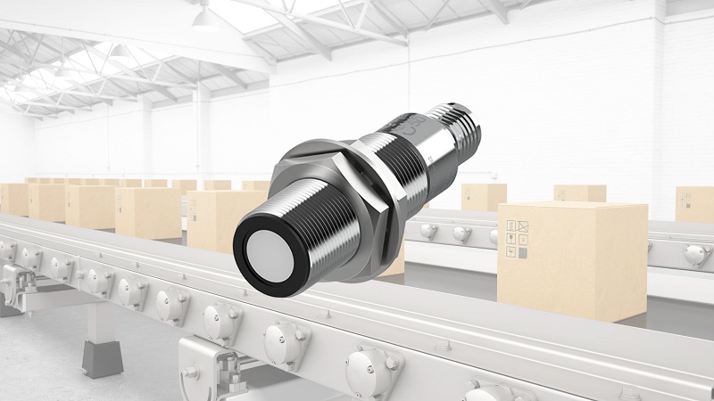
Since the valve bank is a field-mounted device, the physical electrical connections are typically IP-rated M8 threaded connectors, including the network connector.

Figure 3. The control architecture of Festo’s flexible CPX-CP system allows for multiple input and output blocks on the same network address. Image courtesy of Festo
Distributed I/O System
Some manufacturers have a distributed I/O system that is customizable and flexible that connects multiple groups of input sensors and pneumatic valves to one node on the industrial Ethernet network. Festo has developed the CPX-CP system which allows multiple inputs and outputs to be connected to the same network. The CPX-CP system is flexible by design because you can add additional I/O strings that provide chaining of multiple input and output blocks all with the same network address.
In this context, Festo defines a ‘string’ in the CPX system as the cables and modules connecting to one single CP master’s connection point. In other words, a networked branch circuit.
Application
Festo’s style of distributed I/O works well with many input and output requirements spread over a large area. If we were to use isolated individual valve banks we would occupy many IP addresses and connections. Today, this can be very costly as many devices require IP configurations over Ethernet. If we use, for example, three robotic assembly cells all requiring networked I/O controlled by the same PLC, we could use a single distributed I/O system and run one string which consists of inputs and outputs to each robot.
With the CPX-CP system, each string will give you 32 inputs and 32 outputs which is plenty for a robot application. In the PLC, we would only require one item in the network tree, meaning only one IP address and one connection for three robots. This not only saves us on network overhead but also with wiring as each string is only one cable.
Summary
Distributed I/O networks can be used with systems comprising far more than just the pneumatic system emphasized in this article. These networks further consolidate the distributed equipment into a single module to control and monitor all kinds of coils, solenoid valves, sensors, and switches. The technology for valve manifolds has advanced over the years to the point where there are now many options such as distributed or isolated, all with multiple fieldbus capabilities.