Facebook
 Google
 GitHub
 Linkedin
How-To: Programming with IO-Link Devices
Advanced features such as programmable limits, diagnostics, and remote configuration are available with IO-Link devices. Learn how to connect an example IO-Link block into an actual PLC project.

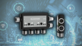
Figure 1. Examples of IO-Link blocks with Ethernet, PROFINET, and other Fieldbus interfaces. Image used courtesy of Balluff
Within any automated machine, sensors detect and measure while output actuators perform actions. The signals from these sensors need to find their way back to the control system via a Fieldbus protocol. There are many different Fieldbus technologies on the market but the popular ones are Ethernet/IP, PROFINET, and EtherCAT. Whichever Fieldbus you choose they all have the same general purpose. To transmit data over a common interface using a common protocol.
IO-Link exists a level below the Fieldbus, connecting individual field devices to a central remote master block, relaying the I/O information to a controller. Why not use a standard remote I/O Unit you ask?
With a typical remote input and output system, you usually only find discrete inputs and outputs, such as sensors or actuators. Extended information such as range data, limits, discrete high/low inputs, and the ability to remotely configure I/O devices are added with IO-Link abilities.

Figure 2. An example system overview of IO-Link under a Fieldbus network. Image used courtesy of IO-Link
IO-Link Infrastructure
An IO-Link system consists of three components; IO-Link master, IO-Link sensors, and the main system controller. All the sensors will connect to the master (the orange networks above) and the master will connect to the controller network (shown in green above). Some masters will reside in an electrical cabinet, but more commonly you will find the master in the field close to the I/O components. Some masters can be added as interface cards within distributed input and output racks.
IO-Link VS Other Protocols
The IO-Link protocol is a device-level point-to-point protocol, so it is restricted to only one device per port. This is different from a Fieldbus technology that would have many devices all connected in star or ring topology with messages being sent out on the network destined to specific devices.
IO-Link Devices and Components
IO-Link compliant devices provide much more than the simple on/off function; you also get configuration and diagnostic settings all over the Fieldbus of your choice. This reduces the integration time of devices, no longer requiring you to manually access and adjust tiny patterns of dip switches. With an IO-Link device, you can configure settings within the PLC program using a Fieldbus message, or sometimes with vendor-specific config software. Some configuration settings can even be set on-the-fly without having to cycle power to the device. The diagnostic data can be used to determine premature wear or to add more descriptions in fault messages.
Connections
Only three conductors are required for an IO-Link device; power, ground, and signal. The signal conductor is a digital switching signal that transmits and receives packets of data from the device or control system - not to be confused with typical 3-wire PNP and NPN sensors. Because of the minimal conductors required and the low current required to operate most field devices a standard M12 screw connector can be used to connect most devices with a master.
IO-Link Programming Example
Once the master and device have been installed, the next step is integration into the PLC program. For this how-to example, assume a Rockwell CompactLogix PLC is controlling a small variety of discrete sensors and several IO-Link compatible field devices.
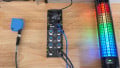
An appropriate choice of IO-Link master might be the Murr Elektronik IMPACT67 (PN 55144), with several digital I/O connections, and up to 4x IO-Link devices.
Each PLC will have a slightly different way of adding Fieldbus devices, with datasheets often providing instructions. In most cases, we can locate an EDS (electronic data sheet) directly from the product site or add a generic ethernet device in the hardware tree, providing the datasheet mentions assembly size data for input, output, and configuration.

Figure 3. Adding the IO-Link master device via the Studio 5000 automation software.
Each IO-Link port contains configuration data, input data, and output data which can be used to set the port as a discrete input or output or to monitor sensor values. If the device is an output, like an actuator, the output block can be used to control the device. Each IO-Link device will have a datasheet that lays out the mapping of the signals or configuration for that particular device (these start on page 69 of the user manual for this particular device, if you wish to follow along).
For this device, controller tag values establish the function of each port. Configuration of each brand and model is different of course, but in this device example, 8 ports exist on the master device.
The first 4, ports 0-3, are for discrete I/O information. This can be either one standard M12 sensor cable on each port, or two separate signals for each port, one on pin 2 and one on pin 4 of each port.
The last 4 ports, 4-7, can be configured for either standard M12 discrete devices, or for IO-Link enabled devices.
This provides up to 12 total I/O devices, in combinations of 1 or 2 per port on the first 4 ports, and discrete or IO-Link on the last 4 ports.
The following image provides, simultaneously, a clip of the datasheet displaying the parameter definitions, the Controller Tag database with the tag names, and the ladder logic command which sets the port (or pin) as an input or output.

Figure 4. IO-Link datasheet (top left), with controller tags for the new device (top right), and an example of setting the IO type via ladder logic (bottom).
The final step is to read sensors or write to actuators on those ports.
Since in the previous step, port 1 was established as an output, we can write to the first output bit using a simple output instruction, as shown in the figure below.

Figure 5. Discrete outputs in the tag database, and a command to energize the first output.
If the device is an IO-Link enabled device, a special IO-Link function parameter can be set to determine those ports as either IO-Link or as standard IO, as with the output set in Figure 5.

Figure 6. Setting an IO-Link enabled device.
Not every device from every manufacturer will be configured by such controller tags. The exact capabilities and configuration details will change, this is simply provided as an example of setting up a single device to monitor and command a variety of devices.
Applications
Most applications in which I’ve used IO-Link devices are for robot end effectors. Typically a robot will come with power and ethernet connections at the upper arm. By mounting an IO-Link master on the arm, you have access to multiple inputs and outputs for gripper functions. All of this capability with only two cables through the robot arm. Other applications would be for modular conveyors, with inputs for pallet present, outputs to lower stops, and RFID readers for pallet tracking. With an IO-Link master, each station can have all the functionality with one connection to the PLC.
Related Content