Facebook
 Google
 GitHub
 Linkedin
Tutorial: Setting up an IO-Link Network With Built-in Logic
IO-Link has established itself as a reliable field network that’s constantly evolving with new generations of devices. Learn how to configure logic directly on the IO-Link master.
Control systems traditionally have several levels of implementation. They could loosely be broken into the following:
- Field-level I/O devices, where we find buttons, valves, and motor contactors.
- Controller level: PLCs and PACs, and sometimes remote terminal units (RTUs) and industrial PLCs (IPCs), all executing command logic
- SCADA level, which includes data collection, processing, historians, and visualization.
These days, this simple architecture is turned on its head, thanks to all the smart devices across the plant system. That command logic level is now found at many levels, not just inside the controller.
Most recently, the trend is to shift control logic down to the lowest reasonable level, much like the human nervous system, where quick reactions happen at the point of application, leaving the main controller to be the gateway, sharing data across the machine centers in the plant or focusing on power-intensive vision or AI execution.
Allowing this logic to execute on a field-level device means that we must understand how to connect the devices, connect the control logic, and apply a function block algorithm quickly and easily.

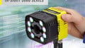
Figure 1. This project uses the new SIG300 from SICK.
For this project, we will turn to the brand-new SIG300 sensor integration gateway from SICK, using a sensor and stack light, both configured for IO-Link.
Connecting to the IO-Link Master
Unlike some control system tutorials, we won’t need a PLC or Ethernet connection for the configuration. The USB-C connection hosts a web server that is accessed over a fixed IP address of 169.254.0.1. Ensure the USB-C cable is rated for data, not just power.
Navigate to that IP address with the web browser, and you will enter the SOPASair configuration software.
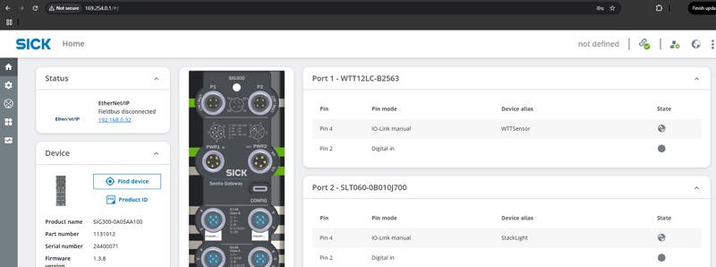
Figure 2. Logging into the web server via USB.
Why is this significant? First, the configuration computer does not need to be connected to the machine network, which protects all of the other devices on that network from being accessed by a potentially unsecured computer. Second, a USB interface requires close physical access, further preventing unauthorized changes to the device. Finally, since the connection is separate, there is no need to disconnect any fieldbus cable in order to connect, so there is no disruption to the machine network.
In the top-right corner, log in to the Maintenance user level with the default password of “main” unless it has been changed. For security reasons, you should set your own password.
Setting up Ports
We first need to configure each port to be IO-Link, digital in, or digital out as needed. Inside the SPOASair interface, navigate to the Ports menu on the left sidebar, where all ports are listed.
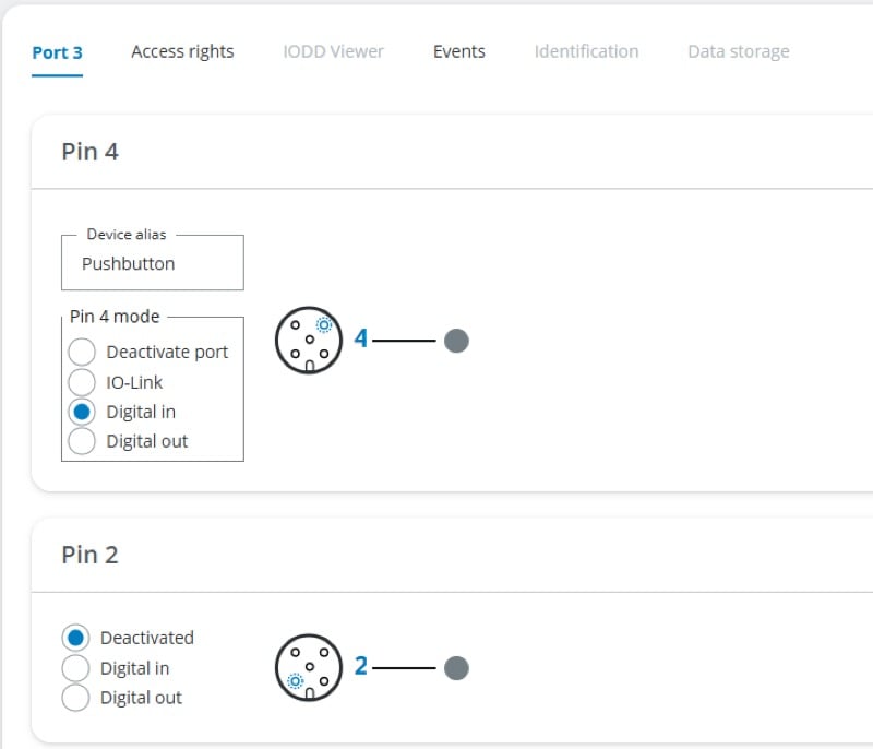
Figure 3. All ports can be configured as IO-Link or as individual digital I/O pins.
By default, all ports are set up for IO-Link, but a quick change can adapt them for digital I/O use. Click the Access Rights tab near the top, and make sure that Sensor Port Configuration is checked for REST API / MQTT / UI. If you want to use an output port in the logic editor, be sure the Write Process Data is checked for the logic editor. Back in the Port tab, you can now toggle between IO-Link, DI, or DO for the various pins.
What About IO-Link Devices?
If a certain port has an IO-Link device connected to it, there is a lot of extra capability that can be added via the IODD view. This IODD is a file called an IO-Link Device Description, found on the website of virtually all IO-Link devices.
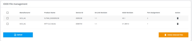
Figure 4. Uploading IODDs.
On the left side, click Application, then IODD File Management. From here, you can upload the IODD of any IO-Link device (from any manufacturer). Back in the Port menu, you can now assign an IODD to a port, so the SIG300 will always know what device to expect.
What can you do with IODDs? Let me give two examples.
First, I have a WTT laser distance sensor. When I assign the IODD and navigate to the IODD Viewer tab, I can see the current status of the triggered outputs, read the analog value, teach the trigger points for the Q outputs, and a host of other functions. These analog and digital outputs will also be available in the logic editor.
Second, I have an SLT tower light. In the IODD viewer, I can select the running mode (level, segment, etc.), configure the colors, adjust the brightness, and more. Depending on the mode (I’m selecting Level mode), the logic editor will contain this light as an output.
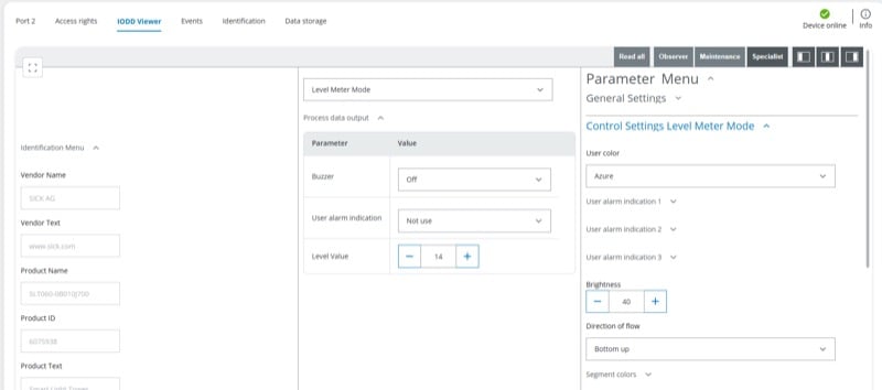
Figure 5. An example of what can be configured in IODD Viewer (this is an SLT light tower).
Constructing and Applying Logic
For this introduction, we will apply a very simple logic program. The analog distance of the sensor will be reflected in the ‘level’ mode of the tower light.
Click Application, then Logic Editor. When the I and O points load, we should be able to find two entries:
- S1 analog value on the left side is the WTT sensor. The S# refers to the connection port on the SIG, so that number may be different. I have my sensor in Port 1. This sensor has a rated range of up to 3800 mm.
- S2 level value on the right side is the tower light output. By default (although you can change this in the IODD Viewer), the tower illuminates each segment in threshold multiples of 5. This is a 20-segment light, so a value of 100 will fully light up the tower. This is important.
Drag the S1 analog value into the workspace, and then the S2 level value. Connect the S1 directly to S2 by clicking and dragging to make a line. Since this is an integer value, it will be dark red.
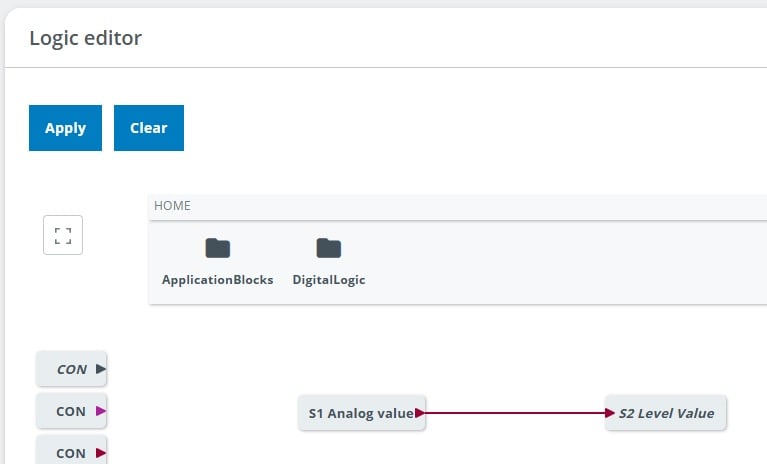
Figure 6. Connecting the sensor directly to the light tower.
Click Apply at the top left, and it will work, but the tower will light up very quickly. This is because a value of 100 mm (which isn’t far) will fully light up the stack.
Instead, let’s divide the sensor value by 10, so that we’ll need to reach 1000 mm for full illumination. You could divide by any number up to 38 (recall the 3800 mm max range), depending on the application you need from this sensor.
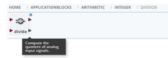
Figure 7. Using a division block to make a more appropriate range scale.
Drag in an integer division block, and follow that with a CON (constant value) from the left side. You’ll notice four different CON blocks, each color designating a data type. Dark red is the correct type for an integer.
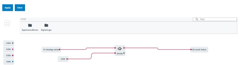
Figure 8. The compiled logic structure for driving the light with the sensor.
With the CON connected to the division block, click the gear in the corner and set a constant value of 10.
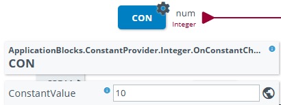
Figure 9. Adding a constant division value of 10.
With this new logic structure, click Apply, and you should have a functioning signal tower driven by the sensor. You can disconnect the computer at this point; the logic is now stored on the SIG300.
A Little Logic Goes a Long Way
By placing the logic as close to the point of application as possible, we can help to manage more discrete chunks of the automation system without disrupting the central controller. One caution, however, is to be sure and carefully document the project; installing logic on multiple devices may become very confusing if not managed properly. Keep this in mind, and you’ll be able to build and maintain really complex systems in no time.
All images used courtesy of the author.