Facebook
 Google
 GitHub
 Linkedin
Considerations for Designing Cleanroom Control Systems
Designing the control systems for a properly functioning cleanroom comes with its own set of challenges and requirements. Here, learn what goes into cleanroom system design and why.
A cleanroom’s environment is controlled so that it has a limited number of particles in the air. Particles cause contamination so they must be limited. That means that the particles are filtered out or restricted from ever entering the cleanroom. Particles can come from dust and bacteria and air clarity is affected by the temperature and humidity in the room.

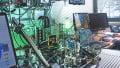
Figure 1. A cleanroom contains an extremely limited number of particles in the air to ensure sterile manufacturing and production.
Cleanrooms are used in various manufacturing industries, like semiconductors and pharmaceuticals, where a high degree of contamination-free environments is the requirement for production, from manufacturing to packaging.
Keeping a cleanroom certified for use in production by the FDA and other governing bodies requires the work of systems engineers, technicians, and maintenance staff. This article looks at the control systems designed and utilized in cleanroom design and maintenance.
Control System for Cleanrooms
As is the case in other industries, the cleanroom industry greatly benefits from automation. Without automation, it would be impossible to fully employ the benefits of cleanroom technology. Different components and monitoring sensors are used to effectively carry out the workings of a cleanroom.
HVAC Systems
As the heating, ventilation, and air conditioning (HVAC) system performs the functions related to air, the HVAC is an important aspect of the cleanroom. Different types of control components are used to control the characteristics of air. Mainly, they comprise of:
- Variable frequency drives
- Airflow sensors
- Differential pressure sensors
- Temperature and humidity sensors
Variable Frequency Drives (VFD)
VFDs are the primary components used to control the air in a cleanroom. They are not only used to start and stop the fan, but their ability to receive feedback from different sensors enables them to control speed accordingly. All VFDs are capable of accepting both 4 – 20mA and 0 – 10V signals, so any other sensors with these same outputs can be used.
Airflow Sensors
Airflow sensors monitor the air flowing inside and outside the cleanroom. The feedback from these sensors is then used to control the speed of the supply air fan, which is operated by the VFD.
If the supply air is less than the preset value, the VFD increases the speed of the fan causing the airflow to increase. Similarly, if the airflow is greater than the preset value, the VFD decreases the speed of the fan, causing the airflow to decrease.
The feedback signal can be a 4 – 20mA current or 0 to 10V. Airflow sensors are installed at the duct of the fresh and return air supply nearest to the controlled area.
Differential Pressure Sensors
Differential pressure sensors measure the difference between two points, not the actual or absolute pressure. In cleanroom technology, the area inside the cleanroom should be at a positive pressure and the area outside should be negative. This is because positive pressure prevents foreign particles from going into the controlled area.
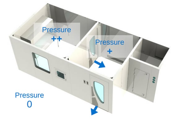
Figure 2. For cleanrooms, the area inside should be at a positive pressure and the area outside should be at negative pressure. Image courtesy of Cleanroom Technology.
A differential pressure sensor monitors for positive pressure in the controlled area and alerts the system if the differential pressure goes negative. These are also used in the filter assembly of the clean rooms. Its purpose is to measure the condition of the filter indicating the effectiveness of its filtering capability. In this case, it is installed across both faces of the filter.
Temperature and Humidity Sensors
Every manufacturing industry enforces strict control of the temperature and humidity conditions within a cleanroom. Any deviation from these parameters can greatly affect the manufacturing process resulting in a defective product.
Temperature and humidity sensors are used to monitors these two physical values. Sensors for both values are built into the same housing and the signal is carried out by the separate conductors.
Either 4 – 20mA 0r 0 – 10V can be used as a signal and is fed to the main controller. Some sensors also have a display attached to the sensor for the visualization of data at the spot. These sensors continuously measure the values of temperature and humidity. Any deviation from the preset values can trigger an alarm. Until the conditions are brought back until control, the system remains in the alarm state.
Alarm Interface
Because so many of the components in the HVAC system must raise an alarm if conditions change from preset values, an alarm interface is necessary so that the proper workers are notified and alerted of the deviation. The alarm interface should be made available in the desired cleanroom area so that the production crew can easily see the status of the conditions. The interface should also be made available in the maintenance control room so that maintenance workers can immediately plan their maintenance activities.
Data Recording
Automatic data recording of the cleanroom conditions helps maintain a consistent environment. It records the physical value of different sensors after set intervals.
External data recorders that can output the data into a printable format or can transfer to data storage devices can also be used.
Control System Algorithm Requirements
Most commonly, the control system's algorithm should be able to:
- Control the fan speed to supply the desired airflow. The feedback is given by airflow sensors. They monitor the physical value with the set value. Any change in the sensory value causes an increase or decrease in the fan speed.
- Monitor environmental conditions like temperature and humidity. Any change in the preset value can trigger an alarm or stop the process.

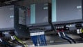
Figure 3. The control system algorithms used must control and monitor a variety of components. Here is an example of a closed-loop control using external sensors. Image courtesy of Cleanroom Technology.
The interface should be easy to operate with clear instructions to ensure understandability by everyone working in the cleanroom, from engineers to production crew.