 Facebook
 Google
 GitHub
 Linkedin
Electric Actuators Designed to Replace Fluids: Hands-on Tutorial
Learn how electric actuators can replace fluid systems with SMC’s e-Actuator series, offering simple setup, clean operation, and accurate motion contro
Electric actuators are emerging as a clean, precise alternative to traditional fluid-based motion systems. Yet many engineers assume they require complex wiring, software, and control hardware compared to the simplicity of pneumatics and hydraulics. In this tutorial, we explore how SMC’s e-Actuator series bridges that gap by combining easy setup with the advantages of electric motion. From wiring basics to software configuration and operating modes, we’ll walk through how to replace fluid systems with straightforward electric control.
Actuators are motors that create motion in a linear direction. To do this, they use screws, belts, and gear systems to convert rotation into straight-line motion.
Historically, the most common way to create linear motion was with fluids–the pressure from air and hydraulic fluid. This is still very common because the systems are easy to create and simple to manage. However, there are a few advantages of using electricity to duplicate this exact same motion.
Electricity can reach remote locations without bulky infrastructure (pumps, compressor tanks, reservoirs, etc). It’s also much cleaner, since fluids often leak and require maintenance. Motors with encoders can more accurately track positions, creating an entire motion profile, not just slamming the actuator from end-to-end.
The downside of electricity, at least for most situations, is that any motion drive systems are very complex: signal cables, configuration software, a controller with a compatible program, fieldbus interfaces, PID loop tuning, and more! In many cases, this is a major barrier to simply swapping out a fluid system for an electrical system.
Some solutions attempt to duplicate the control simplicity of fluids, but with the motion profile advantages of electricity by using electric actuators. We’ll investigate such a solution, the e-Actuator series from SMC.
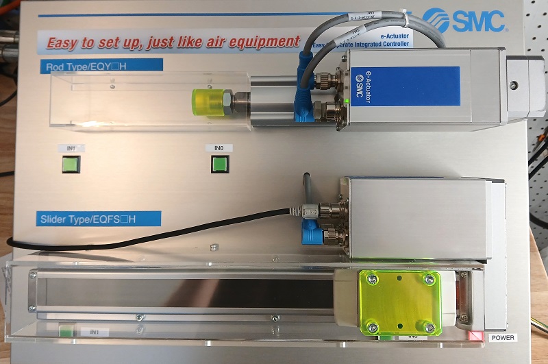
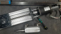
Figure 1. The e-Actuator series in a demo unit from SMC. Image used courtesy of the author
E-Actuator Series from SMC
Motion control is a tricky topic because it spans from a button that makes an axis move, to a complex multi-feedback precision loop with fieldbus communication to a controller.
If the goal is ease of operation, we prefer the former scenario. An electric actuator, wherein a simple button press or digital input from a sensor commands the axis to move to a determined location. That’s it.
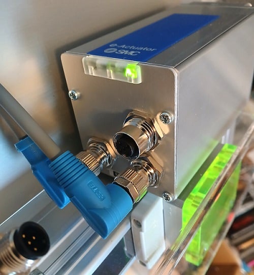
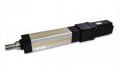
Figure 2. Integrated controller with sockets for power (lower left), I/O (lower right), and the PC connection (upper open socket). Image used courtesy of the author
We will use a slider-type EQFS series actuator (special thanks to the SMC team for loaning a sample for bench-testing). These actuators are not free from complex controllers. However, it’s built right into the actuator and automatically handles all the heavy lifting. A glance at the side of the control module shows one M12 input socket for power, a second 8-pin M12 for the digital I/O signals, and a third M12 connection for the PC configuration connection.
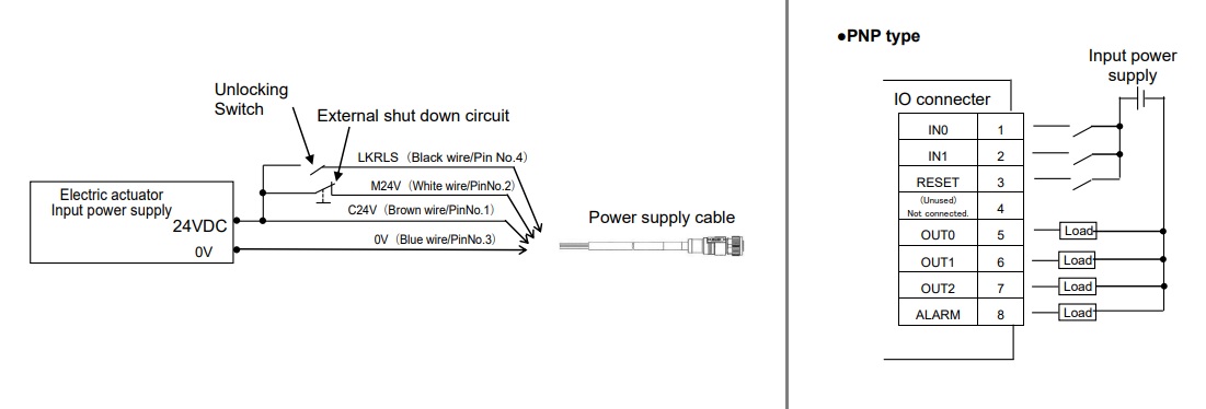
Figure 3. Pinout for power (left) and for I/O (right). Image modified from SMC product user manual
The power input receives +24 and 0 volts from a DC supply.
The signal input has a few more tricks up its sleeve. First, it is important to note that, unlike PLC input modules, the I/O pins are internally connected to the power supply input. Providing 24 volts to an input pin is sufficient; there is no Com terminal. This also means that the external I/O devices must be supplied by the same power supply as the actuator itself, or at least the 0 V rails must be tied together.
The first two pins are for the signal inputs. This will be very significant in the next step when we talk about the configuration software and the various modes of operation.
Software Configuration
Programming the actuators is not complicated. The software is called the e-Actuator Setup Tool, available free from SMC.
Connecting an M12-USB converter cable will auto-identify the actuator type and provide an interface for setting all relevant parameters.
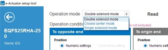
Figure 4. Operating modes. Image used courtesy of the author
Operating Modes
There are three different modes, all of which can be driven with just the two digital inputs.
- Single solenoid mode: energizing IN1 drives the actuator to the far end, then turning it off makes it return to the origin end.
- Double solenoid mode: energizing IN1 drives the actuator to the far end, then energizing IN0 makes it return to the origin end. Energizing both inputs does nothing.
- Closed center mode: energizing IN1 drives the actuator to the far end, then energizing IN0 makes it return to the origin end. Energizing both inputs drives it to a center point.
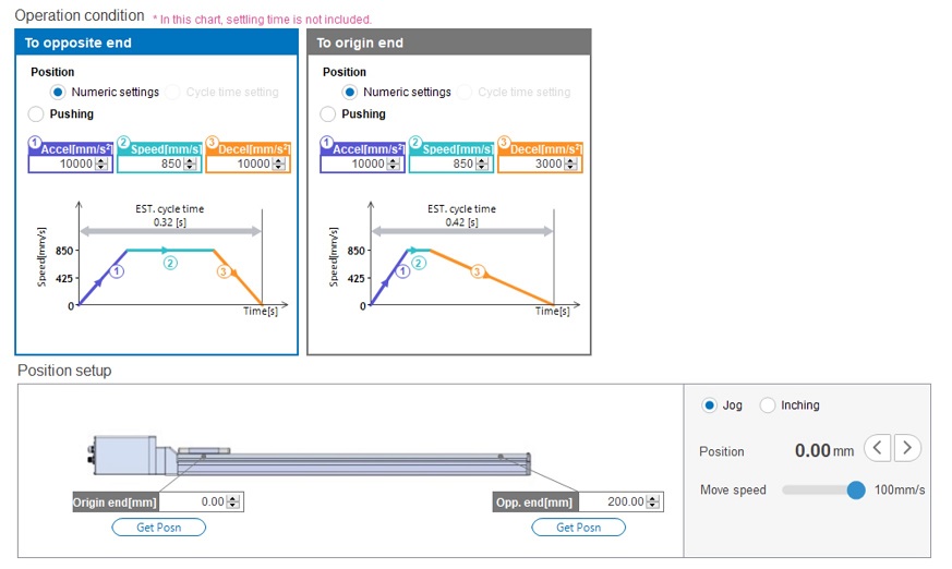
Figure 5. Position and speed settings. Image used courtesy of the author
Speed and Position Settings
The whole idea is to set up a system that is very simple to operate, but that doesn’t mean we can’t configure some of the motion.
First, we can select the speed profile for both directions of motion. Speed profile includes accel, top speed, and decel. It will automatically calculate the total travel time based on these speeds and the stroke length.
Speaking of the length, we can also set the position of the opposite and origin end; it doesn’t need to move all the way to hardware limits. We can also choose the exact intermediate position for the center closed mode.
When the operating mode, speed, and position parameters are set, you can save the data to the device.

Figure 6. Saving data to the device. Image used courtesy of the author
Summary of Electric Motion
Although this motion method is nice and simple, it’s unreasonable to claim that electric is always a better fit. It’s always best to compare the pros and cons of each power method in order to choose the right types of motion systems for each application.


Does it need a calibration after an emergency stop button is pressed or a power loss?