 Facebook
 Google
 GitHub
 Linkedin
Fundamentals of Directional Control Valves in Fluid Control Systems
Directional control valves (DCVs) come in many shapes and sizes for pneumatic and hydraulic applications. Learn to distinguish the different configurations and the meaning of external markings.
Almost any hydraulic or pneumatic system contains one or more of these devices called directional control valves, or DCVs. These valves direct the flow of energy to different actuators in the system that perform work, commonly cylinders and fluid motors.
Components in Hydraulic And Pneumatic Systems
The construction of internal components changes slightly depending on whether the energy medium is compressed air or pressurized hydraulic fluid, or whether the valves are manually vs solenoid controlled.
The terminology and markings used to describe the function and ports of a DCV can be confusing, so I’ll shed some light on what this language means and how to read those cryptic markings correctly.

Figure 1. The solenoid valve is one of the most common sights in a modern pneumatic system. Image used courtesy of Festo
Ports, Ways, And Positions in Valves
Directional control valves are categorized by the number of ports and the number of ways that air or fluid can travel.
A port is a threaded hole in the body of the valve that allows a medium to travel into or out of the valve. Each port will have markings to show the function of the port. Some ports have multifunctions and some have specific functions like exhaust or return ports.
A way is a path through the valve body, the path can change as the valve changes positions. The pathway directs the flow of energy to different ports resulting in different functions.
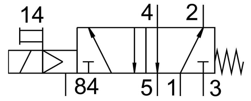
Figure 2. The right side of this diagram shows the port connections. The numbers on the left side are additional pilot air supplies found on some valves. Image used courtesy of Festo
A position represents a function of the valve, typically the valve will only have two or three positions. In each position the pathways through the valve change resulting in a change of function for specific ports.
So how can a valve have fewer ports than ways? Well, it has to do with shared functions of the valve. The return port or exhaust port cannot change function, this means there would need to be multiple return ports to get the fluid back to the tank, which would result in multiple return lines. Some manufacturers have combined the exhaust or return pathways into one port resulting in fewer hoses running back to a reservoir.
The number of ports and ways depends on what device the valve is controlling. A two-port valve is the minimum number of ports a valve can have, and it functions like an on / off valve.
A five-port valve is typically used to control a double-acting cylinder. One port is the supply port while two ports are used for performing work, and two exhaust ports. A two-position 5 port valve can extend and retract a cylinder with two exhaust ports. There are also two-position 4 port valves where both exhaust ports are combined internally so there is only one threaded outlet for exhaust.
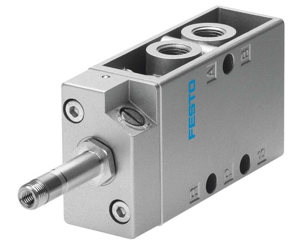
Figure 3. A 3-port valve with input, output, and one exhaust. Image used courtesy of Festo
Control Valve Markings
Some manufacturers put markings on the valve body next to the ports to define the static function of the ports. A two-port valve may only have an arrow on the valve body that shows the direction of flow for that valve. A 5-port valve requires more detailed descriptions for the different ports. Valve markings are fairly standard across manufacturers but they can differ, so always refer to the valve manual for proper connection. Typically there are four markings that can be found on pneumatic or hydraulic.
- ‘A’ & ‘B’: These are the work ports or output ports. If you are controlling a pneumatic cylinder, these ports would be connected to the extend and retract ports of the cylinder
- ‘P’: Refers to the pressure or pump, basically this is the supply port for the valve.
- ‘T’: In hydraulic systems, the fluid needs to return back to the tank, the “T” port refers to the tank or return line. In a pneumatic system, this is referred to as the exhaust port. Sometimes mufflers are screwed into these air exhaust ports and sometimes hoses are used to vent the exhaust air to a safe location.
With these marking being relative to hydraulic systems, some manufacturers will alter the makings to represent pneumatic systems. Instead of using ‘T’ for tank, ‘EX’, ‘E1/E1’ or ‘R/S’ might be used to represent exhaust. The ‘P’ marking could mean pressure or pump, but some manufacturers will use ‘IN’ to indicate where the input pressure medium should be connected.
Numbers are frequently used as well to indicate the connection ports.
- 1: Input, equivalent to ‘P’ or ‘IN’
- 2: First of the work output ports, equivalent to A
- 3: Exhaust for port 2
- 4: Second of the work output ports, equivalent to AB
- 5: Exhaust for port 4
These seem to be placed in a random order, but note that for 3-port valves, only the first three numbers are used and the definitions remain true.
P&I D Documentation
A piping and instrumentation diagram is a document that is used to describe a pneumatic or hydraulic system. The ways, ports, and port markings are typically shown on the drawing to ensure the valves are correctly plumbed. Sometimes the markings on the valve do not match the indicators on the P&ID document (like if the valve was replaced by a similar model from a different manufacturer). For this reason, it is important to recognize the type of valve by the symbol used, not only by physical markings.

Figure 4. Example diagram drawing of hydraulic directional control valve use. Image used courtesy of Wikipedia
Pneumatic And Hydraulic Systems
Pneumatic systems are commonly used on automated equipment found on just about every factory floor, and hydraulic systems are commonly found in process automation and testing facilities.
There are some occasions where pneumatic and hydraulic systems will cross over on the same equipment, and while hydraulic and pneumatic components are vastly different, the symbols and connection logic used on schematics as well as the markings on the valves can be similar. Always ensure valves are connected correctly and all connections are secure before adding pressure to any system.


I’d like to add two practical details that may be missed by someone like me who’s only occasionally had to deal with pneumatics:
1: The photograph depicts a valve with two actuators, meaning it has a neutral position and two directions. The symbol depicts a valve with one actuator meaning it defaults to an active position. This means that a driven cylinder will actively move to its “base” position if power is lost. Occasionally this may be desirable behaviour in order to drive a system to a safe state if control is lost, but more often it risks causing unexpected motion. It also means that in the event of a pipe break there may be no way to isolate the cylinder unless there is an upstream valve.
When driving anything of significant size it is sensible to assume the need for a two actuator valve, it can be swapped for a sincle actuator type if power-loss behaviour later turns out to be desirable.
2: Many multi-way solenoid operated valves use a smaller solenoid operated valve to drive a cylinder that moves the main valve. I believe this is called “pilot-operated” but Google invariably leads me to Three Mile Island so I struggle to find relevant search results. In pneumatic valves the feeds to the other valves are often hidden, built into the valve body or the manifold, but where a valve is used in an unusual way it may be nessecery to break out these feeds and supply them separately, for example if the system pressure is unsuitable or if a medium other than compressed air is being routed.