 Facebook
 Google
 GitHub
 Linkedin
Guide to Wiring: Conductor Materials, Styles, Sizes, and Best Practices
The simple tasks can lead to the most failures. Basic practices in the wiring assembly stages of a project can lead to long-term success or haunting tales of intermittent yet persistent failures.
It’s tempting to just use the spare wire lying around the workbench for electrical projects, but there are some serious considerations that must be addressed first. Proper wiring can make or break an electronics project, becoming the difference between a working, efficient system and a fire hazard.
Depending on the size of the project, applicable building and electrical codes, and other criteria, the material, style, and size of the wire must be chosen carefully.
Wire Materials
For most applications, copper wiring is the preferred wiring material. It has low resistance, is relatively corrosion resistant, dissipates heat, and can provide many years of good service. The downsides to copper wiring are the expense and the weight, as copper is dense.
Aluminum wiring is sometimes used, though it has fallen out of favor for many applications. Aluminum oxidizes more easily, forming an insulative layer. Unlike rust, aluminum’s oxide layer is uniform and serves as a protective layer. This protective oxide layer does not allow easy transfer of current or heat. To combat this, aluminum wiring is coated with a conductive compound that limits oxidation. After a few years of service, the compound can dry out, creating hot spots in the wire.
As an anecdote, the author’s first apartment had aluminum wiring. His father, an electrical engineer, remarked, “Hmm. I thought all the places that used aluminum wiring burned down.”
Silver, gold, some brass alloys, and a few other materials are used for more specialty options. However, wiring materials should not be mixed. Mixed metals in contact can lead to galvanic corrosion, which will cause one of the wires to be selectively attacked. Even splice connectors must be carefully selected based on the appropriate material combinations.

Figure 1. Various sizes and types (stranded and solid) wire on display. These samples are all copper. Image used courtesy of Adobe Stock
Wire Styles
The two fundamental wire types are solid and stranded. Solid wires contain one single piece of wire that travels the entire length of the run, whereas stranded wires contain many smaller gauge wires all packaged in one insulated sheath.
Solid wires are used for more permanent installations, where wires will not be subject to movement. They are often stiffer and harder to bend than a similarly-sized stranded wire. However, solid wires work really well with spring, screw, and friction clamp terminals, as the entire wire end is placed in the contact.
Stranded wires are more commonly used for general-purpose installations, as they are more forgiving in applications where the wire may be moved. Components on robots, motors, moving platforms, and other such applications would cause solid wires to fail through fatigue. Stranded wires are more likely to flex and resist this type of failure for the same thickness. For spring, screw, and friction clamp terminals, stranded wires can be slightly more complicated. Often, individual strands separate from the bundle and are not clamped properly.
Wire Size
Wire size is typically specified as a gauge; the smaller the gauge, the larger in diameter the wire. While virtually any gauge can be manufactured, most applications call for 4/0, or 0000 (0.46 in diameter) down to 32 gauge (0.008 in diameter). The ampacity, or safe current-carrying capacity of the wire, is a function of its diameter or gauge. Ampacity is specified by the National Electric Code (NEC). For a more detailed chart of gauges and diameters, check out the handy table on AllAboutCircuits.
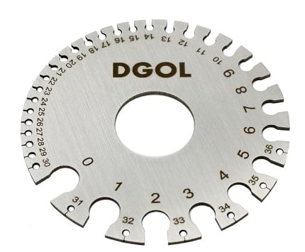
Figure 2. Tool for measuring wire gauge. Image used courtesy of Amazon
If a specific application requires more than 380 amps, the maximum limit for 4/0 wire, then a copper bus bar should be used instead.
At the opposite end, any smaller than 32 gauge, and the wire becomes very hard to handle, as it breaks under as little as 1.8 lbs of tension force. If an application calls for smaller wires, they are typically either embedded traces on a printed circuit board or a conductive paste squeezed out of a syringe.
The cross-sectional area is used in many parts of the NEC, particularly as it relates to space in a conduit. Depending on the circumstance, only a certain amount of conduit area can be occupied by wire.
The wire thickness also impacts the so-called “skin effect.” The skin effect is the idea that the current actually flows on the outside edge of the wire. The depth in the wire penetrated by the current is a function of the frequency, where higher frequencies do not penetrate as deeply. Even though the wire may have a large diameter, only the surface is being used when the voltage oscillates at high frequency. This shows up as a higher resistivity, meaning more of the signal is converted to heat, rather than being transmitted through the wire. Therefore, bundles comprised of thinner stranded wires are preferred over solid wires for high-frequency applications.
Good Wiring Practices
Regardless of the type and material of wire used, good wiring practices make or break the connection, often quite literally. During installation, the stripping of insulation from wires is one of the easiest places to compromise wire integrity.
Selecting the Proper Strip Size
It can be tricky to pick the gauge in the wire stripper. Inexpensive tools may not have the correct gauge size, or the cutting blade may not be sharp enough to properly cut the insulation. If the strip gauge is too small, it may result in tiny nicks in a solid wire or entirely severed conductors from a stranded bundle. If the selected gauge is too large, the insulation will turn white where it is stretched. In either case, it is better to cut the wire and start over than to try and salvage a damaged wire.
Completely Cutting the Insulative Jacket
It is better to make several “cuts” with the wire stripper, with the tool being turned all the way around the wire, or at least clamped several times. Clamping down once and then attempting to pull the insulation off will lead to stretched insulation more times than not.
Proper Stripping Length
For every device, the proper amount of wire must be stripped. Consider the application and remove only the necessary amount of insulation. Often, there is a mark on the device itself with a strip measurement mark. More than one technician has shorted closely-spaced wires in a controller due to over-stripping of insulation.
Tinning the Wire
Although it is usually an optional practice, it sometimes helps to “tin” stranded wire. Tinning involves lightly coating the wire with solder. This helps speed up and ensure soldered connections and helps keep the bundle of strands together for spring clipped and screw terminal connections.
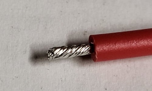
Figure 3. Properly cut, stripped, and tinned wire. Image used courtesy of the author
Color Coding and Labeling the Wires
Just like proper documentation, all wires should be labeled and color-coded whenever possible. This will save a ton of time during troubleshooting. There is no official color coding, outside of a few exceptions, and so placing adhesive labels on both ends and along wires can help clear up confusion.
Good Wiring is Up to YOU
Good wiring choices and good wiring practices will enhance any installation’s longevity. Proper choices in the wiring and assembly stage are usually not a very complicated issue, but some planning early in the project can save the design engineer lots of time during startup, integration and troubleshooting later.


Slightly surprised I didn’t see any mention of using ferrules as an (industry standard) alternative to tinning stranded wire for use in spring and screw terminal applications.