Facebook
 Google
 GitHub
 Linkedin
How to Convert Gray Code to Binary for Encoders
The sensors in absolute encoders output Gray code sequences which require some complicated conversion methods to be properly used. This article shows how to take the Gray code used by absolute encoders and convert it to binary.
For most rotary motion using motors and servo mechanisms, feedback is critical. This feedback is most often in the form of an encoder. For many encoders, the output is ‘absolute’ which means that the exact degree of position can be measured at any time, but it comes with a drawback: it requires a lot of sensors. These sensors often output Gray code sequences which require some complicated conversion methods to be properly used.
How Binary Causes Problems With Encoders
The most common form of feedback for motors and other rotating motion devices is the encoder which uses light (optical) sensors against a rotating disk with particular black and white patterns to provide angular position data. Two main varieties of encoders exist: incremental and absolute. Incremental encoders count light/dark mark transitions to track how many degrees of rotation that have passed in a given time.
The other kind of encoder is the absolute type, and this kind is frequently used because it can measure the same quantities as the incremental type, but it is constructed with a disk that has a complex pattern of marks radiating from the center. The pattern is entirely unique depending on the position. They most often have between 256 and 1024 different unique patterns equally distributed around the circle, indicating either an 8-bit or 10-bit output respectively.
The number of bits equals the number of sensors that are tracking the pattern, and this number of sensors can create a time-consuming task for a single processor to read. To minimize reading errors, it is common for the disk to have a pattern that would only allow one single sensor reading to change at any time as the disk is rotating.
Since the patterns are only dark or light, this gives an on/off or ‘binary’ output for each sensor. In typical binary patterns, the bit sequence directly corresponds to an equivalent decimal number which would increase around the disk, from 0 up to 256 (or up to 1024). The only problem with a standard binary sequence is that multiple bits change simultaneously for many of the counts. Each time that happens, this is likely to encounter a reading error.
The following table shows how often this occurs.
| Decimal | Binary | |
| 0 | 0000 | |
| 1 | 0001 | |
| 2 | 0010 | 2 changes |
| 3 | 0011 | |
| 4 | 0100 | 3 changes |
| 5 | 0101 | |
| 6 | 0110 | 2 changes |
| 7 | 0111 | |
| 8 | 1000 | 4 changes |
| 9 | 1001 | |
| 10 | 1010 | 2 changes |
| 11 | 1011 | |
| 12 | 1100 | 3 changes |
| 13 | 1101 | |
| 14 | 1110 | 2 changes |
| 15 | 1111 |
As shown, this possible error happens every other count, which is entirely unacceptable.
Why Is This Such a Problem?
As an example of the severity of this error, imagine the transition from the ninth to the tenth pattern. The four sensors would initially read 1001 and then become 1010 a moment later as the motor spins.
A controller would read the sensors at regular rapid intervals, so it might likely begin reading while the pattern is still on nine, so the first three sensors may read 1 0 and 0. Then, just before it reads the final sensor, the pattern steps up to 10 and the final sensor becomes 0.
The controller would string that entire sequence together as 1000. But that looks like it just went backward, back to eight! That’s not what actually happened.
On the other hand, if only a single bit transitions from one count to the next, the controller will either see the change and recognize the motion, or it will not see the change and recognize that no motion has happened quite yet. Gray code is this systematic sequence of only one change at a time, but for a professional familiar with standard binary, this pattern seems foreign.
| Decimal | Binary | Gray Code |
| 0 | 0000 | 0000 |
| 1 | 0001 | 0001 |
| 2 | 0010 | 0011 |
| 3 | 0011 | 0010 |
| 4 | 0100 | 0110 |
| 5 | 0101 | 0111 |
| 6 | 0110 | 0101 |
| 7 | 0111 | 0100 |
| 8 | 1000 | 1100 |
| 9 | 1001 | 1101 |
| 10 | 1010 | 1111 |
| 11 | 1011 | 1110 |
| 12 | 1100 | 1010 |
| 13 | 1101 | 1011 |
| 14 | 1110 | 1001 |
| 15 | 1111 | 1000 |
Although it does not match standard binary, the Gray-code-to-binary calculation can be done quite simply, and here are some examples in standard ladder logic, and in structured text using C++.
Ladder Logic Conversion
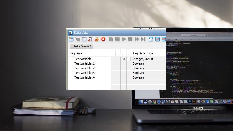
To convert the Gray code bits into the proper binary bits, each Gray code sensor must correspond to a Boolean value, either directly from the sensor, or as part of an integer.
This example is written in a ladder programming software from Automation Direct and assumes that ‘Sensor_1’ is the Least Significant bit (LSB), the sensor along to the outside edge of the encoder disk. There are eight total sensors (8-bit) increasing into the center of the encoder.
‘Binary_Number:1’ is the corresponding bit of an integer used to store the standard binary equivalent. For other software, such as Rockwell’s RSLogix, this integer bit might look like Binary_Number.0 where Binary_Number is an INT type tag, starting at bit 0.
- Line 1 - For proper conversion, the most significant bit (MSB) which is Sensor_8, remains the same.
- Line 2 - For the next significant bit, a logical comparison of ‘Exclusive OR’ is used between Sensor_8 and Sensor_7. This will return a 0 if Sensor_7 and _8 are both the same, and will return a 1 is Sensor_7 and _8 are different.
- Line 3 to 8 - For every remaining bit, we continue to use an ‘Exclusive OR’ between the previous bit and the next Sensor value.
If the encoder is 10-bit, there will be 10 lines, and the first two lines will use Sensor_10 and _9 and descend until the last sensor is finally used.
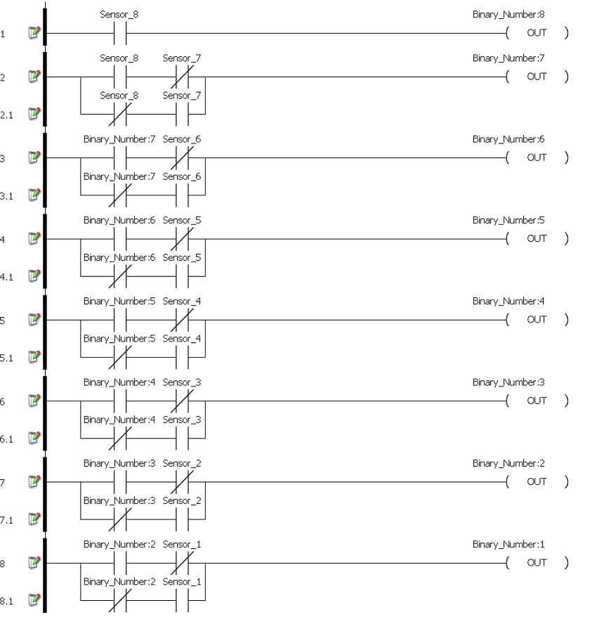
Figure 1. An example of ladder logic used in a ladder programming software from Automation Direct.
All of the preceding logic lines may be wrapped into a single custom instruction block or subroutine to simplify the process.
Structured Text Conversion
This example will only be partial since there is a wide variety of languages, syntaxes, and applications. The core objective remains to convert the sensor readings from the eight sensors into the equivalent binary numbers.
For C-based languages, the Exclusive OR (XOR) to produce a single bit is !=. The MSB is the same as the sensor value, the second bit is the XOR of the two sensors, and every remaining bit is the XOR of the previous bit and the next sensor.
void conversion(){
Binary_Number_8 = Sensor_8;
Binary_Number_7 = Sensor_8 != Sensor_7;
Binary_Number_6 = Binary_Number_7 != Sensor_6;
Binary_Number_5 = Binary_Number_6 != Sensor_5;
Binary_Number_4 = Binary_Number_5 != Sensor_4;
Binary_Number_3 = Binary_Number_4 != Sensor_3;
Binary_Number_2 = Binary_Number_3 != Sensor_2;
Binary_Number_1 = Binary_Number_2 != Sensor_1;
}
The remaining step is to convert the Binary_Number bits into an integer as appropriate for an application. Note that different languages may follow various procedures. This example serves only to give an outline of what the process might look like.