Facebook
 Google
 GitHub
 Linkedin
How To Use Analog Inputs With 2, 3, and 4 Wires
Analog inputs are used to measure changes in process through sensors, subsequently converting that signal to voltage or current and sending it to modules that measure this change to determine new setpoints.

Figure 1. Many remote and local I/O systems can use discrete and analog input signals.
What Is an Analog Input?
An analog input is an input to a control system that varies in voltage or current. Analog input signals are commonly used with sensors that measure the surrounding environment. Some common examples are temperature, pressure, humidity, and frequency. As the sensor detects a change in the climate it measures, the output from the sensor will change. There are a couple of different types of analog inputs. In this article, I will outline some of the differences between analog input signals and all the different connection styles that should be understood.
When dealing with input or outputs, you always need to consider the reference device since a sensor might consider its signal to be an ‘output,’ but a controller would register that same sensor signal as an ‘input.’ In this article, I will refer to input referenced to the PLC and outputs referencing the device connected to the input.

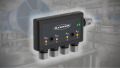
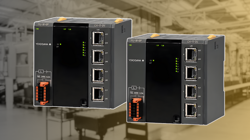
Figure 2. Siemens S7-1500 analog module. Image used courtesy of Siemens
Analog Transmitters and Signal Conditioners
Most true analog input sensors, like thermocouples or resistance temperature detectors (RTDs), do not source enough current for a standard analog input to be able to detect. In this case, a transmitter or conditioner is used to amplify the signal to more industry-standard voltages or current. When selecting a transmitter, you will need to know what kind of out signal your input module will accept; 4-20 mA and 0-10 VDC are common input signal types.

Figure 3. Programmable temperature transmitter to convert the output of resistance temp sensors into an analog signal. Image courtesy of Wika
Selecting an Analog Input Module
There are a couple of types of analog input modules to choose from, and when selecting the correct module for your system, there are some considerations. The sensors or transmitters used in the system will typically output 4-20 mA or 0-10 VDC, and it is common to use 4-20 mA and keep a common signal style throughout your system.
Typically, analog modules may be purchased with either two or four channels, with the cost increasing along with the number of channels. Another option is to source a configurable analog module. These modules can be configured for current or voltage inputs; some can even be configured for input or output functions.
Wiring the Input Devices
In a similar vein to analog outputs, there are 2-wire, 3-wire, and 4-wire input wiring styles. The difference between these inputs usually lies in the original power source, less in the nature of the signal. A 2-wire uses the same two wires for signal and power with a shared ground. A 3-wire sensor will have a wire for power, a wire for signal, and a shared common wire for ground. A 4-wire device has an isolated power and ground from the signal power and ground.
With analog signals susceptible to electrical noise, a shielded cable with a drain wire should be used for any analog connections. Also, ensure the drain wire is connected to the designated terminal or the chassis ground. Refer to the sensor or transmitter’s user manual for proper wiring.
Below is a diagram from an Allen-Bradley Point I/O analog input module, showing a 4-wire and 2-wire configuration for current inputs.

Figure 4. 4-wire and 2-wire current inputs. Image used courtesy of Rockwell Automation
The 2-wire configuration on the right side receives its voltage from the module, as shown, or from an external power supply with a common C connection and usually includes a chassis ground terminal for the shield drain wire, which is not included as part of the conductor wire count. In this circuit, the input device is simply a variable load resistance with a supply voltage and output current.
A 4-wire device (on the left side) has a +/- supply connection and a separate set of output current and common return connections, giving a total of 4 wires. Note that the power is provided by the module in some cases, and in other cases, as shown below, the power supply is external. However, in either case, the number of wires to the input device is 4.
The analog voltage input module has a similar wiring diagram with optional voltage DC supply terminals, with the below diagram showing a 2-wire input on each side.

Figure 5. 2-wire voltage inputs. Image used courtesy of Rockwell Automation
In the final case of a 3-wire sensor, this is most familiar to control technicians. A supply and common ground from the module (or power supply) provide power, while a third wire supplies the analog signal. A final chassis shield drain may be a connection point, but it is not counted among the wires.
The Siemens’ analog input module has a very similar approach for voltage measurement but a slightly different approach for the current configuration. The inputs can be configured for voltage or current with this particular module.
In the module below, a number of individually isolated 2-wire voltage connections provide a variety of inputs. In non-isolated modules, a single common connection provides a voltage baseline for all input signals.
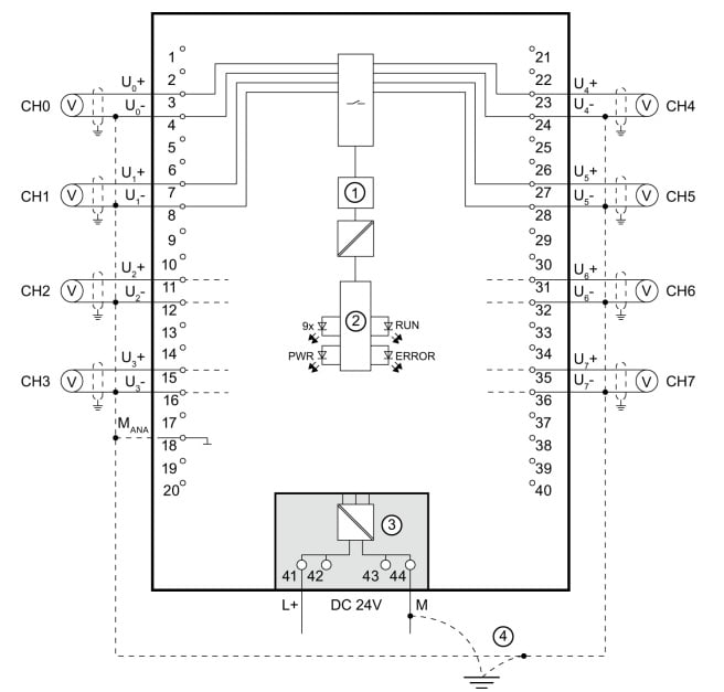
Figure 6. Eight isolated voltage inputs CH0-CH7. Image used courtesy of Siemens
The diagram below shows connecting a 2-wire, 3-wire, and 4-wire load. Because the module is configurable, there are many terminals, so refer to the manual and match your particular input device with the correct configuration.
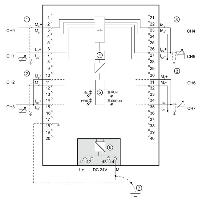
Figure 7. Various analog connection methods including 4-wire (1), 3-wire (2), and 2-wire (3). Image used courtesy of Siemens
Specialty Input Modules
Some measurements are very common, and manufacturers have made special analog input modules to accommodate these common sensors. A common temperature sensor is an RTD, which is a resistor that changes resistance as the temperature of the environment changes. Another common temperature sensor is a thermocouple. This sensor consists of dissimilar metals that output a small voltage as the environment's temperature changes. Most control system manufacturers will offer an analog input module specifically made for these sensors.
The diagram below is a configurable input module from Siemens showing both thermocouples and RTD. With these special modules, there is no need for a transmitter or signal conditioner. The sensor can be wired directly to the module, and the signal can be scaled in the programming software to engineering units. These specialty modules can save money, but if your system has a mix of temperature and other measurements, it may not be beneficial to allocate a slot in the I/O rack just for one type of measurement.

Figure 8. Temperature inputs including thermocouples(1) and (2) and RTDs (3). Image used courtesy of Siemens
Analog Input Connections
Analog inputs can be either current or voltage and are commonly found as either 2-wire, 3-wire, or 4-wire devices. Although the compatibility is the same between various makes and models, there are differences in common notation and wiring options, so be sure to verify each connection with proper wiring diagrams.