Mitsubishi HMI Programming Tutorial: Controlling On/Off Bits
Learn how to use GT Designer 3 to create an interactive control system on Mitsubishi HMIs. With practical examples of simple on/off bits, gain some understanding of HMI designing and programming.
Interacting with human-machine interfaces (HMIs) in industrial control systems is one of the most engaging aspects of the system. HMIs come in different sizes and brands, providing the capability to not only control but also monitor essential parameters of the system. This tutorial will focus on how you can set up and program HMIs in the Mitsubishi Electric family using GT Works’ GT Designer 3 and GX Developer.
Learning a new system can be challenging, but once you get the hang of it, the concept cuts across many different HMI brands. To better understand the concepts in this tutorial, we are going to implement a simple step-by-step example of how to control on/off bits using GOT (graphics operation terminal) series Mitsubishi HMIs and the GT Designer 3, GOT screen design software.
Creating a new Project in GT Designer 3
Before getting started, one of the prerequisites to consider is to have the latest versions of GT Designer 3 and GX Developer software. If possible, it may also help to have the MELSEC series PLC and a physical GOT HMI, but don't worry, as we will also look at how you can carry out simulations without needing a physical PLC or HMI panel.
Once you have GT Designer 3 installed, you can launch the application to create a new project. A pop-up window with the title 'Start New Project Wizard' appears in which a new project can be set up. The wizard allows for setting up parameters like the type of GOT system, controller, GOT IP address, screen switching device, and screen design.
In the new project wizard, we can set our HMI series to GOT 2000, the set-up direction to horizontal, and name our package folder 'tutorial'. For the controller type to be connected to GOT, a selection can be made from a wide range of popular PLC brands like Siemens, Omron, and Mitsubishi Electric, among many others. For this tutorial, we are going to use a Mitsubishi Electric PLC (MELSEC FX series) and the GOT 2000 series HMI.
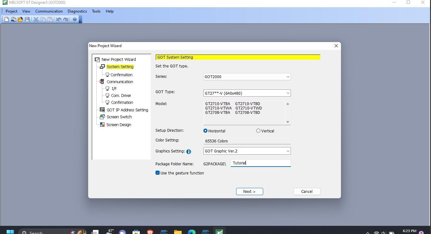
Figure 1. New project setup wizard.
Once the GOT and the controller type are set, you can click 'next' to choose the connection interface (I/F) from a drop-down list of a range of communication protocols for data transfer between the GOT HMI and the PLC. For our case, we are using the RS-232, one of the standard I/F for the MELSEC-FX series. Once this is done, we can choose the screen design and finally confirm the system environment setting by selecting ‘finish’.
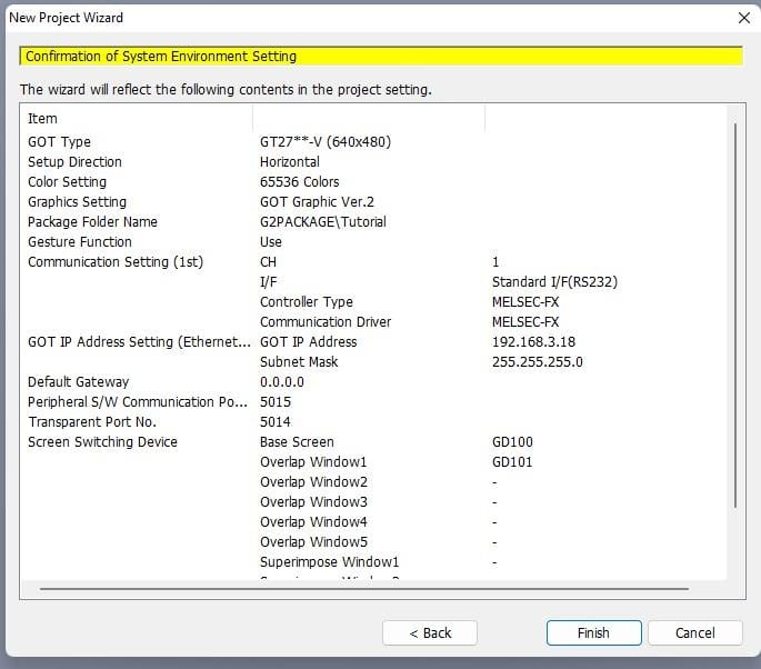
Figure 2. Project parameters.
Adding a Button and a Bit Lamp
With the new project setup complete, we can then create an interactive button to control the status of a bit lamp. Under the object tab, select 'bit switch' and place it in any position on the base screen. A switch is much like an illuminated pushbutton that will send a high or low signal to a corresponding bit in the PLC, and can also be lit like a lamp from a bit in the PLC.
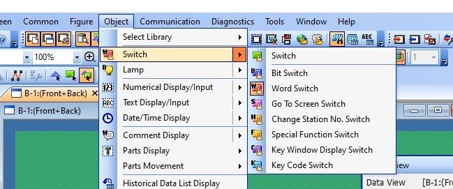
Figure 3. Adding a bit switch into the HMI project.
Under the same tab, a bit lamp can also be added on the base screen. The lamp is only an indicator light, responding only to the status of a bit from the PLC.
Once the two objects are added to the design window, addresses can be added for identity and must correlate with the ones connected to the PLC I/O. In our case, our HMI design will have the bit switch with the address X000 for ON/OFF functionality.
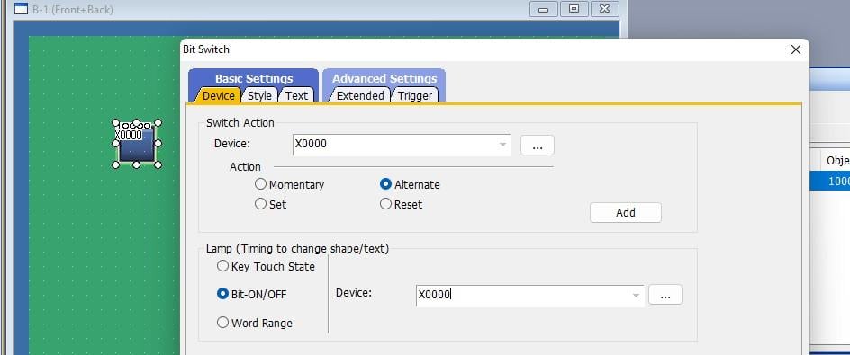
Figure 4. Setting the address for the bit switch in the HMI project.
For our bit lamp output, we can add the address Y000 by double-clicking on it to open a setup window like the one shown below. The lamp type is Bit, and the address is added in the textbox just beside the word 'Device.’
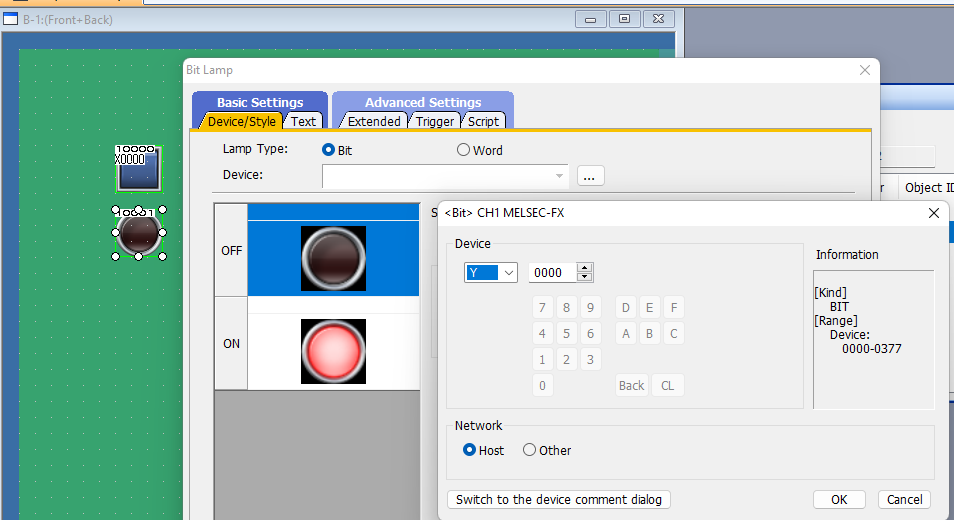
Figure 5. Adding a bit lamp and setting the address in the HMI project.
Once the addresses are added, the design is now ready to be written to the HMI. To do this, click on the communication tab which you can then click 'write to GOT' to write the design to the HMI panel. Alternatively, the icon circled in red in the image below can also be clicked to upload the design to the HMI. With the design uploaded, a ladder logic program is written and uploaded to the PLC where the lamp is connected to Y000 on the PLC output so that it can turn ON when X000 is clicked on the HMI panel.
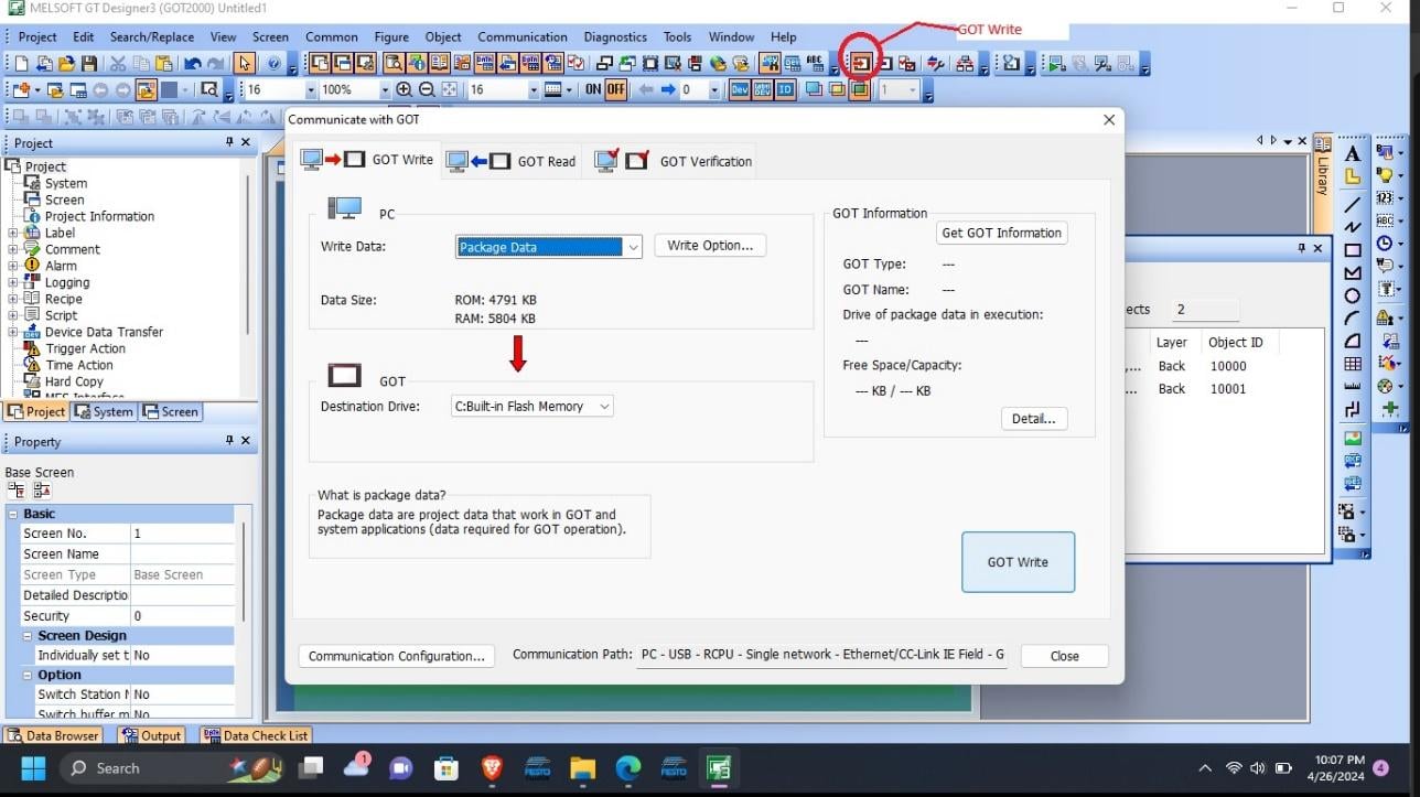
Figure 6. Writing the GOT project to the HMI.
GOT Simulator 3 and GX Developer
Suppose you do not have the PLC hardware, but you still wish to test the functionality of your design? GT Designer 3 can work together with a ladder written in GX Developer and GT Simulator 3 to simulate and monitor the output of the design.
Following the design example we created earlier, we can simulate the ON and OFF status of the bit lamp using GT Simulator 3 and a PLC program written in GX Developer. To do this, launch GX Developer and create a new project, setting the PLC series as FX series and naming the project ‘tutorial’. Write the ladder logic program shown below taking note of the I/O addressing. Finally, click on the simulator icon to launch the GX Simulator.
To learn more on how to use GX Developer, check out our previous introduction article getting started with GX Developer and GX Simulator.
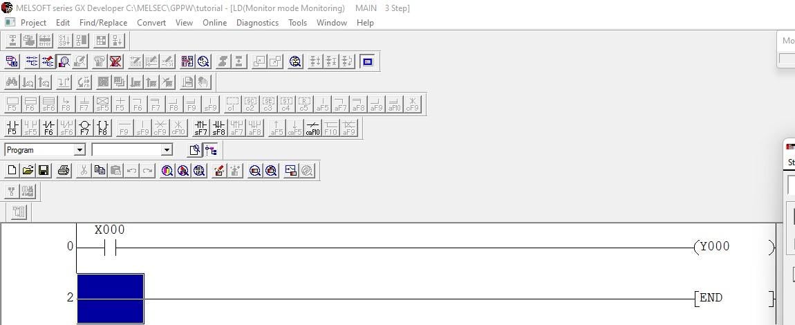
Figure 7. The PLC project to match the simple on/off bit test on the HMI.
With the ladder written and GX Simulator activated, we can now launch GT Simulator 3 by going to the tools tab then 'activate simulator,' or simply use the keyboard shortcut ctrl+F10.
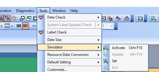
Figure 8. Activating the HMI simulator.
Once activated, the GT Simulator window opens showing the bit switch and the bit lamp and when the switch is clicked the lamp changes to a brighter color to simulate ON status. The object simulation of the HMI also directly affects the status of the ladder logic written in GX Developer as shown below.
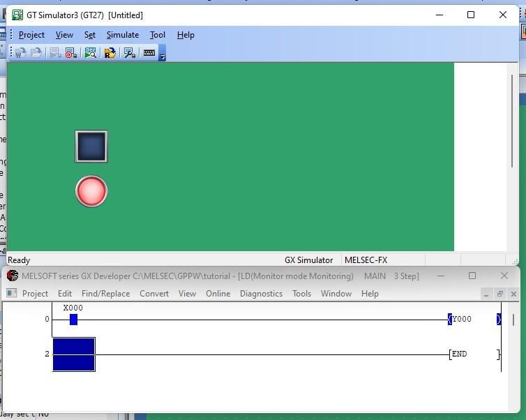
Figure 9. Overlay of lamp and ladder logic when the bit is energized.
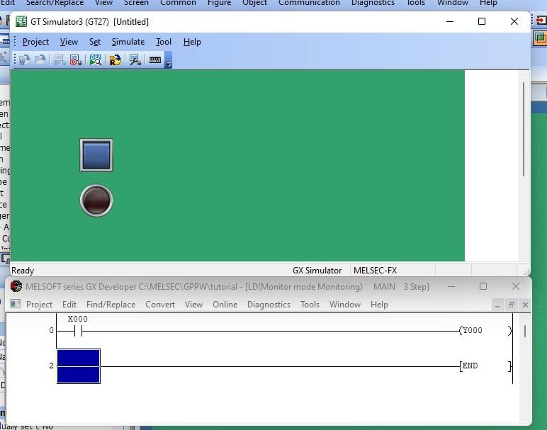
Figure 10. Overlay of lamp and ladder logic when the bit is de-energized.
Advancing with Mitsubishi HMI and PLC Programming
Having taken your first step in learning how to use GT Designer3 to design interactive elements in Mitsubishi HMIs, you are now ready to challenge yourself with additional HMI elements and more complex PLC instructions. This may seem challenging at first, but with constant practice in creating more interactive projects, you will soon be an expert in GOT series HMIs and other models as the knowledge cuts across a range of HMI platforms.
Stay creative and happy programming!
All images used courtesy of the author