Facebook
 Google
 GitHub
 Linkedin
Network Manager SCADA System in Hydroelectric Power Plants
Network Manager SCADA is a real-time, modular system that is highly scalable and easy to deploy and maintain. The system can grow with future needs and support a virtualized environment to decrease hardware cost.
This article presents and explains the functions and operations of Hitachi’s Network Manager SCADA platform. This product is an essential component for the successful operation of energy and transportation systems. Understanding the components of a SCADA system will help an engineer become more familiar with similar situations and platforms.

The Network Manager SCADA platform plays an essential role in the successful operation of energy and transportation systems, such as in hydroelectric power plants. Image used courtesy of Canva
The Network Manager product was made available in 2003, following the selective merger of two real-time control systems, S.P.I.D.E.R and Ranger, both released to the market in the 1990s. These consisted of an energy control system and Supervisory Control And Data Acquisition (SCADA), designed to cover a wide range of electrical applications. The concept was based on the standardized modular package tailored to customers' functional and performance needs, utilizing their different functionality.
Network Manager SCADA is a real-time, modular system coupled with cyber features designed for a wide range of control and monitoring applications, electrical networks, power generation, transmission, and distribution systems. The solution is highly scalable and easy to implement, deploy, and maintain. The system can grow with future needs and support a virtualized environment to decrease hardware cost.
Network Manager supports the multiple redundant schemes equipped with modern Human-machine Interface (HMI) WS500 workstations. The Network Manager product package also includes third-party software products. The latest release (called NM 10.3) from Hitachi Energy (earlier owned by ABB) uses the following main third-party software products:
Third-party Softwares |
Client/Server |
|
Internet Explorer 11 |
Utility Data Warehouse (UDW) explorer |
|
Office 2016 |
HMI Client |
|
Oracle 19c |
(Data Engineering) DE server, UDW |
|
PostgreSQL 11 |
UDW |
|
PCU 9.2.2 |
Process Communication Unit (PCU) |
|
Redhat Enterprise Linux 7.4 |
SCADA/EMS/DMS server, PCU, UDW |
|
VMware E-SXi 5.5.0 |
Virtualized system |
|
Windows 10 2016 |
HMI Client, DE Client |
|
Windows Server 2016 |
DE, Domain Controllers, PCU, WS500 Thin client Server, Central Backup |
Network Manager SCADA System Configuration
The following main applications and services-like database management system (DBMS), authentication/authorization, data acquisitions, and engineering tool are part of Network Manager SCADA System:
-
RCS Application running in application servers
-
Avanti for real-time database management
-
SCADA servers: Red Hat Linux (nmaas01,nmaas02)
-
Utility Data Warehouse: Red Hat Linux (nmaudw01), RAID Controller, Oracle for archiving
-
PCUs also called Front End Protocol Handlers (nmapcu01 and nmapcu02)
-
WS500 HMI Client for graphical display
-
Active Directory Servers (nmaad01 and nmaad02) for network and operator related authentication and authorization
-
Data Engineering (DE) servers (nmade01) for engineering related work
-
HP Data Protector for system image backups and restoration
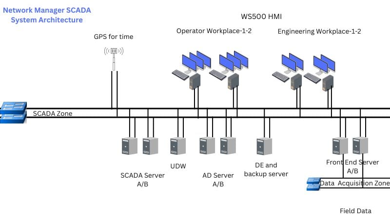
Figure 1. Network Manager SCADA system configuration and architecture.
Data Engineering DE400 Tool
The DE400 is the data engineering application running on Windows Server 2016 used to enter data into the Network Manager control system. Network control systems require an immense amount of static information like text and symbols describing the network components. The information consists of descriptive data and of displays representing the network. Both forms of information need to be consistent, easy to enter, and easy to update. Drawing the network specifies the topology (electrical connectivity), and the data for each object is then entered using object-specific forms called DE Form, as seen in Figure 2.

Figure 2. DE400 Form for entering object information like breaker and isolator.
A network component is an object that is displayed in the world picture by a graphical representation and is stored in the maintenance database (MDB). For example, a station or a bay is a network component displayed as a rectangle, and a switch is a network component represented by a symbol. The network components displayed in the world picture are created according to the following hierarchical levels:
-
Station
-
Subnet or transformer
-
Bay
-
Element
The graphical components are objects that are not network components, but are required for the picture layout, e.g. labels, static texts, navigation buttons, symbols, lines, etc.
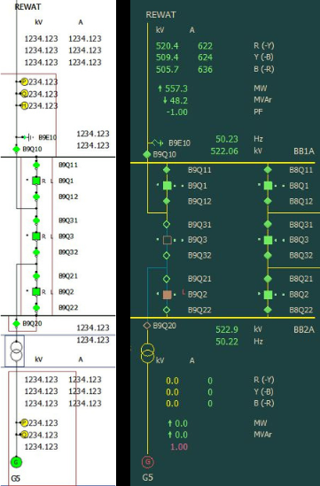
Figure 3. Network Topology and components created in Graphical Editor (GED) on the left and Realtime Display in HMI WS500 on the right.
Referring back to Figure 2, the single bay named B09 with three individual breakers (CB Q1, Q2, and Q3) was created. Now in Figure 3, they can be seen as the squares in the center listed as B9Q1, B9Q2, and B9Q3. This is a part of a 500 kV switchyard, one-and-half busbar scheme. In this bay, one transmission line and one generating unit are connected.
PED500 Picture Editor (PED)
PED500 is one of the Windows-based, offline maintenance tools for creating pictures, symbols, and symbol tables. It is a design tool for the creation of any type of graphical picture to be used in the WS500 Operator Workstation (HMI). PED500 supports Microsoft Windows type of functions like Undo, Cut, Copy, Paste, Delete, Edit, Group/Ungroup, and Draw Order (Bring Forward/Backward, etc.).

Figure 4. PED500 basic tools bar.
PED500 is used to create new picture displays and to edit existing picture displays. The more exciting features are tabulated below:
-
Office style tool for creating display windows look and feel, dockable toolbars, and tooltips.
-
Intuitive and easy-to-use software focused on usability.
-
Importable file formats like .bmp and DXF
-
Multiple displays that can be edited simultaneously and cut and paste between displays.
-
Pictures saved in two separate files, i.e. dynamic reference definition in ASCII format (.ref) and static displays in binary format (.ppi)
For analog value, PED500 supports several presentations like a numeric, bar chart, etc. and the user can easily append engineering units, flow arrows, and symbols. The tool also supports embedding active X control like Dial and Pic chart, tabular grid, transformer tap position, and trends. Discrete elements are breakers or isolators presented with symbols from symbol tables.
After creating the display, two files will be created from the chosen picture name. For example, if the picture is saved as display0101, two files will be created called display0101.ppi and display0101.ref. In order to check any error in the file, picture linking is performed, just like compiling a piece of code for any errors. The picture link log file will be created in the directory with error details. After the final picture generates without errors, the new display will be saved on the SCADA server for runtime live display.

Figure 5. Creation of display in page template in PED500 tool for Hydroelectric Unit.
Maintenance Environment to Runtime
After all the work that has been done in the DE Form, such as object information entry and creation of busbar topologies including station, bays, and elements, as seen in Figure 1 and 2, it's time to populate all engineering work saved in the maintenance database (MDB) into the SCADA applications servers running the ABB proprietary database called Avanti. All data from MDB and pictures created in PED500 are available in the Avanti database after population. All the real-time information from the process is saved in the Avanti database, and database information is fetched by WS500 HMI graphical display.

Figure 6. The population of the new dataset from maintenance to runtime environment for operator
WS500 HMI Client
The Operator Workstation WS500 is a high-performance, full graphics HMI solution for the supervision of physically distributed processes. WS500 is the interface to all ABB Network Manager Applications which provides common user-interface services. Its menu-oriented structure is based on Window interface guidelines for software design. The operator station clients can be set up in multiple ways to meet different demands.
The local client installation of WS500 the most common and is called a rich client. It supports as many screens as supported by the PC, however, the number of WS500 instances is restricted to six per PC. WS500 is easy to use because of the Microsoft Windows user-interface style. Online and customizable, it is possible to make user-specific changes to menus, colors, and many functions, controlling parameters from configuration dialogs without any custom programming.
Scalable SCADA System
The Network Manager SCADA System has come a long way since its release in 2003. The real-time modular system grows with users' needs and improves the control and monitoring of power system applications.
Related Content