Facebook
 Google
 GitHub
 Linkedin
Predictive Maintenance: Defect Analysis Using Electrical Current
Electrical signal analysis has come to the forefront of predictive maintenance, helping to reduce downtime in industrial manufacturing by remotely identifying problems with electric motors and generators.
Unscheduled downtime constitutes a significant problem for industrial manufacturers; a lack of planning for maintenance can lead to a drop of 5 to 20 percent in productivity, leading manufacturers to lose over $50 billion annually.
The actual downtime cost is not just the direct costs incurred with unscheduled downtime but adds the cost of resources, machines, and labor wasted during downtime. It should also include the cost of lost business opportunities. In essence, the true cost of downtime is much more than estimated.
Manufacturers would love to reduce unscheduled downtime—to zero if possible. Predictive maintenance assists manufacturers in minimizing downtime and improving machine operations.

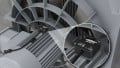
Figure 1. Rather than focusing solely on mechanical aspects, electrical signature analysis identifies problems with the electrical side of machine operations. Image used courtesy of Canva
Predictive Maintenance
Predictive maintenance aims to forecast future faults in machine operations. Condition monitoring is the process of continuously monitoring the parameters of the machine under operating conditions. This real-time data is obtained from sensors attached to the machine. Modern monitoring software can also be utilized for condition monitoring.
Most condition monitoring solutions focus on the mechanical aspects of machine operations. Some of the most common parameters included in condition monitoring are:
-
Position
-
Vibration
-
Speed
-
Temperature
-
Humidity
In recent years, electrical signal analysis has come to the forefront of predictive maintenance. Electrical signature analysis can identify problems with the electrical side of machine operations and is widely used for the same. But they can also detect faults in the mechanical aspects of the machine. Monitoring these conditions is helpful in predictive maintenance.
Electrical signature analysis monitors the condition of electric motors and generators. In most instances, current signature analysis monitors electric motors and VFDs. Similarly, voltage signature analysis is more prevalent for monitoring electric generators. The benefit of using electrical signal analysis is that you need not be close to the machine to perform condition monitoring. You can monitor the current feed from a remote location to detect various types of faults. In this article, we cover electrical system analysis for motor systems.

Figure 2. Multiple techniques can be used to process current signals which are then analyzed in MCSA. Image used courtesy of Canva
Motor Current Signature Analysis (MCSA)
Current sensor signals are used for current signature analysis. A signal processor processes this signal from the sensor. This processed signal is analyzed in MCSA. Some of the techniques that can be used to process current signals are:
-
RMS
-
Fourier transform
-
Time-frequency
-
Wavelet
-
Park’s vector
-
Higher-order stats
The basic concept of condition monitoring relies on comparing real-time data with a historical record of laboratory testing and experience data. The basic concept remains the same for condition monitoring with motor current signature analysis. Laboratory testing gives the current signature when the motor runs in ideal conditions. It also provides the current signature when the motor has some faults. This library of current signatures can be compared against the live feed of the current signature from the motor being monitored.
For MCSA, the supply current must be monitored, meaning the stator current. When a fault occurs, it is reflected in the stator current for an induction motor. The stator winding is used as a transducer. The current sensor is coupled to one of the phases of the three-phase supply to the stator. Depending on the specific use case, this could be a Rogowski coil or a Hall effect sensor. Hall effect sensors are used because of the wide frequency range.
The signal from the current sensor passes through a signal conditioner. The spectrum of available frequencies is analyzed using a spectrum analyzer. The result is fed to the computing system which compares it against recorded current signatures. This comparison will shine a light on the fault that has occurred.

Figure 3. Current sensing alternatives include the multimeter current adapter based on the Rogowski coil principle (left) and the analog AC/DC current sensor using the Hall Effect method (right).
Theory
The supply current to the three-phase induction motor consists of two components.
-
Magnetizing component (IsM)
-
Torque producing current (IsT)
Similarly, torque consists of average and oscillating torques due to torsional vibrations at three frequencies.
$$T_0; T_1cos(2\pi f_1t + \phi_1); T_2cos(2\pi f_2t + \phi_2); T_3cos(2\pi f_3t + \phi_3)$$
Mechanical components with three defects will produce a loading torque on the coupling with the motor. The three frequencies f1, f2, and f3 represent three mechanical defects. T1, T2, and T3 represent the three torques corresponding to each of the mechanical defects with frequencies f1, f2, and f3. These load torques influence the supply current to the induction motor. The following equation represents the magnetizing current and torque-producing current due to these mechanical defects.
$$I_{sM} = I_{sM0} + I_{sM1}sin(2\pi f_1t + \phi_{M1}) + I_{sM2}sin(2\pi f_2t + \phi_{M2}) + I_{sM3}sin(2\pi f_3t + \phi_{M3})$$
$$I_{sT} = I_{sT0} + I_{sT1}cos(2\pi f_1t + \phi_{T1}) + I_{sT2}cos(2\pi f_2t + \phi_{T2}) + I_{sT3}cos(2\pi f_3t + \phi_{T3})$$
Adding the two components will derive a long equation with the components (fe - f1), (fe + f1), (fe - f2), (fe + f2), (fe - f3), and (fe + f3). Here fe is the supply frequency. f1, f2, and f3 are the defect frequencies. Current components with the defect frequencies mixed will be measured. Frequencies [fe ± f1,2,3] can be observed in the current spectrum. The sideband component's torsional vibration across supply line frequency is the strongest indicator of faults in mechanical systems. Analyzing supply line frequencies against reference frequencies stored in computers can be used to identify faults by just monitoring current.
Some of the faults that can be analyzed with motor current signature analysis are:
-
Static air-gap irregularities
-
Dynamic air-gap irregularities
-
Broken rotor bar
-
Cracked rotor end-rings
-
Stator faults such as opening or shorting of coils of stator phase winding
-
Abnormal connections in stator windings
-
Bent shaft resulting in friction between stator and rotor
-
Damages to stator core and windings
-
Bearing failure
-
Gearbox defects
Wrapping Up
The common practice in condition monitoring for predictive maintenance relies on monitoring mechanical properties such as position, vibration, temperature, speed, etc. However, this requires the technician to be close to the machine. Electrical signature analysis helps to monitor and detect faults by measuring the electrical characteristics of electric motors or generators. This can be done remotely without being next to the machine.