 Facebook
 Google
 GitHub
 Linkedin
Should I Connect the Commons or Not? Power Supplies Across Systems
When dealing with two or more I/O systems, the subject of power supply commons will arise. Sometimes the solution is simple, but it can require creativity to find the best (and safest) solution.
Recently, I was working with a system that contained some electric actuators, a PLC, and a few various I/O devices. Nothing out of the ordinary at all, but there was a bit of a twist that made me stop and think about the ways in which we power our control systems.
The twist was this: the electric actuators (e-Actuators from SMC) receive single-ended input signals from the controller. The common connection is established inside the motor drive with a separate 24 v power supply. The wiring diagram in the manual looks like this:
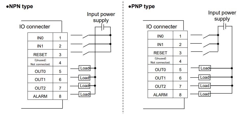
Figure 1. I/O connector diagram. NOTE: There is no connection to a common + or -. Image from SMC product datasheet
This can be confusing to those familiar with PLCs and remote I/O because the power or ground is always connected via a common terminal on the module. Field device power is never supplied through the backplane or bonded with the power supply module. But in some peripheral modules, like this drive, we do see those internal connections.
The benefit of this strategy is that the wiring is simpler, as there will be one less connection for the signal cable. If you need two inputs (IN0 and IN1), you only need to worry about those two wires, nothing more.
However, the tradeoff is that the designer must ensure that the signal is coming from a source that shares the same input power supply as the motor drive. This fact is also noted in the manufacturer's docs:
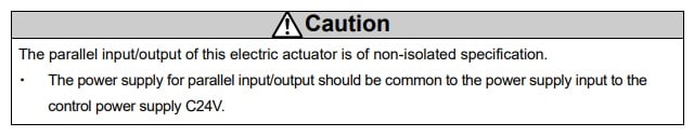
Figure 2. Manufacturer’s note that I/O power supply and controller power supply should be common. Image from SMC product datasheet
Standard Scenario: One Power Supply
This is by far the easiest solution because it doesn’t require any work. If the PLC and the field power to the I/O devices are fed by the same power supply as the motor drive, the current will complete a full circuit and there will be no issue.
The scenario becomes more complex when there are two or more power supplies, and there can be several reasons for this. Perhaps the motor drive is supplied with 48 volts instead of 24. Or the drive electronics are contained inside a box with no immediate access. Or, perhaps the distance between drive and I/O is very long, and heavy power demands are at both ends, requiring separate supplies. Whatever the reason, this option must be considered.
Most Simple: Connect the Common Grounds
In most situations, there will be at least one open terminal block in the control cabinet that is connected to the (-) of the power supply. Even if not, a new one can be placed beside an existing block and jumpered to provide the common connection.
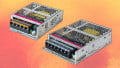
Many power supplies even include an additional (-) that can be used to parallel the power supplies.
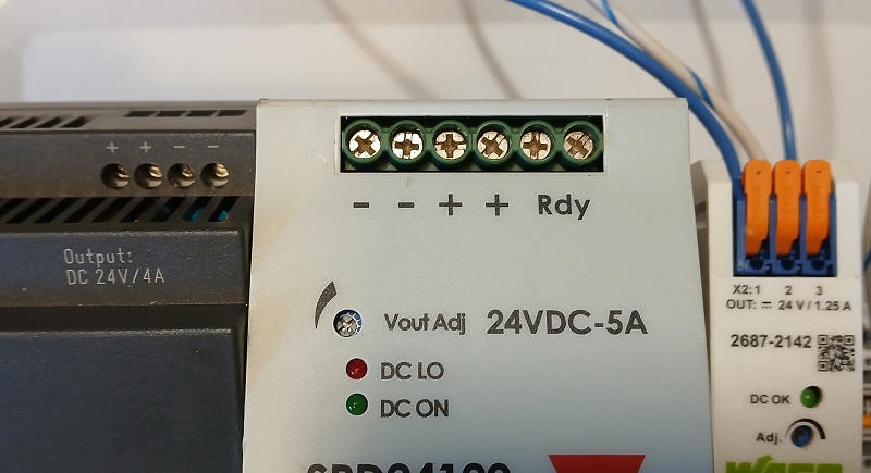
Figure 3. Many power supplies contain 2x or even 3x (-) terminals to link multiple systems. Image used courtesy of the author
Using this terminal block or (-) on the power supply, a single wire can be spanned to connect the (-) of the drive supply to the (-) of the PLC field I/O supply.
More Complex: Access Only at the Coupling
What if the drive system is in a location that has no spare terminal blocks, and there is no room to add more? Are there alternatives to somehow access the (-) of the power supply?
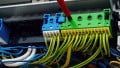
The power connection to the device is usually a type of M12 connector, which is an industry standard. The point at which the M12 cable plugs into the socket of the drive might be a great place to secure the common connection. An M12 splitter, like a Y, T, or pigtail style, can allow the user to access a (-) connection without disrupting the wiring inside the control cabinet.
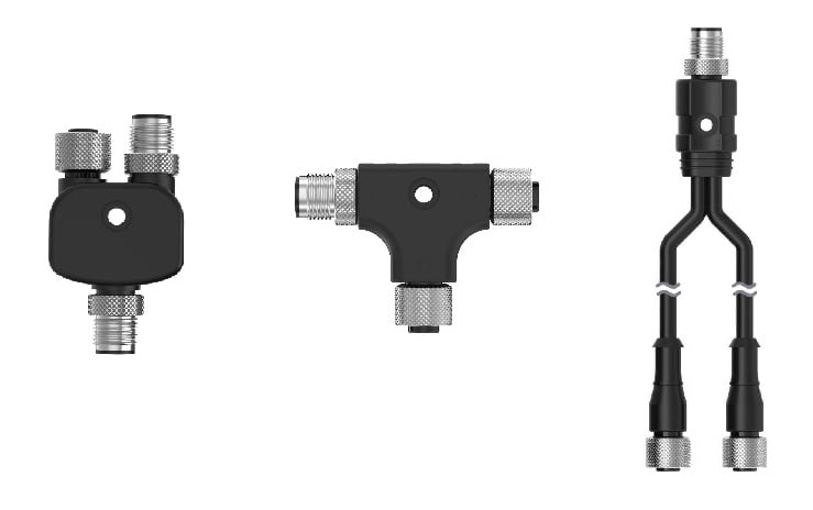
Figure 4. Many options exist for splitting M12 cables: (L-R) Y-splitter, T-splitter, and pigtail splitter. Image (modified) used courtesy of Banner Engineering
It is highly inadvisable to locate a (-) wire, cut it, and insert a splice connector. These can damage the cables and will create confusion by adding unlabeled wires into the cabinet. M12 splitters are secured with threaded connections for security, and the wires can be clearly labeled.
Most Complex: Dealing With Networked I/O
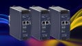
Many I/O devices now run on branching networks between nodes and controllers. A couple of great examples are IO-Link and Modbus, both of which offer plentiful examples of remote I/O hubs. When the wiring datasheets of these are examined, there is a difference between the power input for the processor and the power provided to the terminals (field power supply). Some PLCs even include isolated terminals for module vs. field device power. When faced with both of these, do they BOTH need to connect to the common (-)?
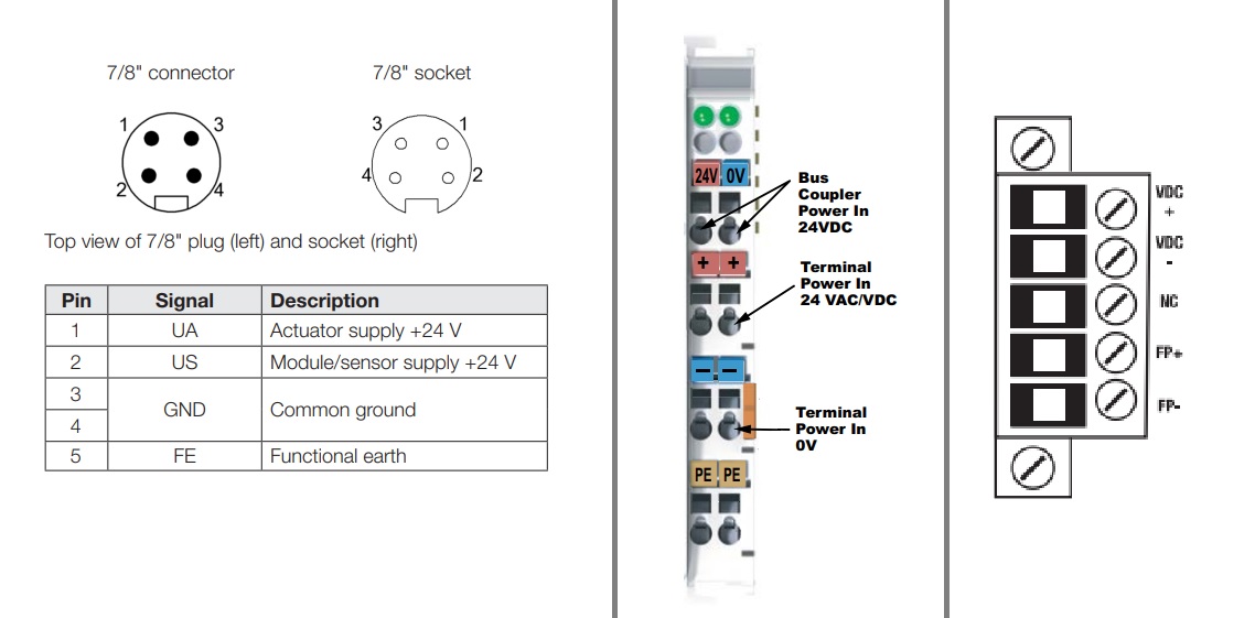
Figure 5. A few examples of devices with separate supplies for powering the module vs powering the field device terminals: (L-R) IO-Link master from Balluff, remote I/O from AutomationDirect, PLC from Rockwell.
The answer is no; only the field power supply will provide the voltage for digital signals at the I/O terminals. Therefore, only the field power supply must share a common (-) between the module and the remote drive that receives the signals.
To explain further, the supply that powers the CPU or the network is irrelevant. None of that power is transferred to the I/O terminals. Only the field power supply must share the common connection.
To Connect or Not Connect?
This short article outlines just a few of the cases where common terminals must be joined. For all the wiring situations out there, certainly there are other rare situations that are not addressed here.
Unlike the common question of grounding power supplies, this matter is not up for debate. If two isolated systems need to share digital signals, the power supply (-) terminals must somehow be tied together. The best solution accomplishes this task with standard, reliable components that are well-documented and labeled, but above all, they provide a safe working environment.


One thing I want to add although it is off the topic but still related to controls systems which utilities AC power sources.
DON’T CONNECT TOGETHER THE COMMONS OF DIFFERENT SOURCES.
WHY?
Fun write up!! To ground, or Not to ground is the question.
I have worked in a multitude of jobs across multiple industries.
My Answer: Single point ground to earth! Other grounds never should go to other grounds