Facebook
 Google
 GitHub
 Linkedin
Techniques for I/O Mapping in PLC Programs
I/O mapping is the process of converting raw input and output data into specific tags, but how can we find a method for mapping I/O that is both efficient and scalable?
What Does it Mean to Map I/O?
Mapping inputs and outputs in a control system means converting the raw I/O values into usable data. The data is then used in the station-level control logic to perform actions or display statuses. When mapping inputs and outputs for machine automation, you will want to ensure that the process is scalable and can be reused for future projects. You might also want to automate the process to reduce integration time.
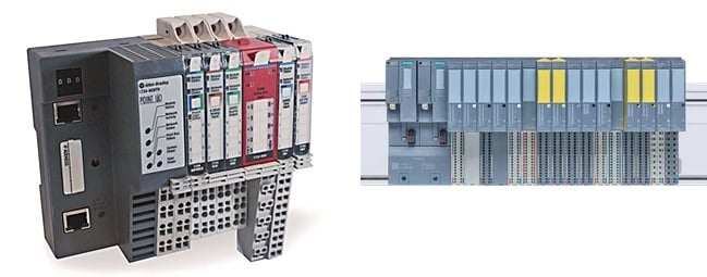
Figure 1. Examples of common remote I/O systems. Images used courtesy of Rockwell Automation (left) and Siemens (right)
I/O Signal Types
There are a variety of ways to send and receive signals from a PLC. Remote I/O racks, Field I/O blocks, and local I/O cards are just some of the ways we connect sensors or actuators to our control system. All of these devices represent their data in the control system in the form of bits (or bytes or ints, depending on the configuration and the type of I/O used).
The tag name for each I/O is derived from the name of the module used to communicate with the I/O device. For example, if you named your input card “InputCard1,” then the control system would populate a byte with the same name. Each bit within that byte represents one discrete input signal. Some machine builders might use the device name from the electrical prints along with, perhaps, the number of the page on which the device is found.
While this raw input can technically be used within your logic, comments would need to be given to each bit to describe the action of that input. The tag name “InputCard1.0” doesn’t tell me what that input is for, or how it is used within the system. Writing comments on thousands of input signals across many different input modules would consume many hours.
Below is an outline of two different methods that I have found useful over the years.

Figure 2. At the top, a UDT is defined for station IO that contains two UDTs, one each for inputs (lower left) and outputs (lower right). Image used courtesy of the author
Types Of Mapping
Depending on the control system and the device used, there are a few different ways to map I/O signals.
Mapping I/O Tags at Hardware Configuration
TIA Portal for Siemens PLC programming provides an embedded system for mapping signals right at the device level. You can choose to use PLC tags, or you can build a custom UDT and data blocks. Each input or output can then be assigned in the hardware configuration.
B&R PLCs provide a similar function, where variables can be chosen for each input or output signal directly in the hardware configuration. This can save time and facilitate faster offline programming. With the open architecture of the B&R platform, you can also automate this process by matching the syntax of the hardware config file.
AutomationDirect also includes the utility to name each point directly when I/O modules are added to the hardware configuration at project creation.
Mapping I/O Tags Manually in Ladder Logic
Rockwell Automation control systems do not offer a hardware-level mapping feature, any mapping that needs to be done is typically programmed in a sub-routine before and after the sequence logic.

Figure 3. The process of manually mapping a single bit to an output coil. Image used courtesy of the author
To reduce the number of tags used, it can be beneficial to create a user-defined type that will house all of the station or machine inputs and outputs. In my experience, I like to create an input UDT and an output UDT, then a station UDT that only has two tags: “i” and “o,” with the newly created input and output UDTs. The “i” and “o” tags will consist of all the different inputs or outputs used within that station. Now, with one tag, I can access all of my station-level inputs and outputs by name.
The mapping takes place in a sub-routine called “Input Mapping” and I use a copy instruction to copy the raw data into my input tags. In the “Output Mapping” sub-routine, I copy my station output tags into the raw data tags.

Figure 4. Using a single line of logic to copy a DINT from an input module directly into a DINT with descriptive tags. Image used courtesy of the author
If you want to use a more generic method you could create a UDT that doesn’t use the input and output names but rather a double integer type (DINT) for the “i” and “o” tags. This will give you 32 inputs and 32 outputs for each station. Comments can then be given to each bit representing the action that is connected. The mapping would similarly take place as described above.

Figure 5. For complex systems, mapping I/O from raw data to logical names is critical. Image used courtesy of Unsplash
Why All The Trouble?
So why spend all the trouble creating UTDs and specific tags when the input value is readily accessible? It all depends on your application.
If you are building a simple garage door opener, then use the raw values. If you are automating a project with many stations, maybe including robots and many input and output devices, you will need to stay organized with your I/O. Tag names for I/O signals can be customized and shortened when using a mapping scheme.
Machine builders keep the I/O organized for modularity purposes and also so that maintenance staff can easily find sensors within the code or in the field. Automating the generation of I/O mapping helps reduce integration time and those automation projects are made much easier when the I/O is organized consistently.
For your next automation project, spend some time and think about how you are going to lay out your I/O and if it is beneficial to map the I/O into specific tags.