Facebook
 Google
 GitHub
 Linkedin
The Importance of Air Preparation in Pneumatic Systems
Compressed air is a common economical way of adding motion to your automated equipment, but the air needs to be filtered, regulated, and sometimes lubricated. The air prep unit does all that and more.
Automated equipment often uses compressed air to provide motion, cool components, or even dry wet surfaces. The factory typically has an air compressor supplying compressed air to the equipment through pipes and values.
Preparing Air for the Point of Application
Once the air has reached the equipment, it must be regulated, filtered, and sometimes lubricated. These are the tasks accomplished by the air preparation unit, sometimes referred to as an FLR (filter, lubricator, and regulator). After the FLR, the compressed air can be reliably used in valves with intricate pathways to direct the air into cylinders, air knives, or air motors.
The FLR protects these devices with the use of a filter and regulator to ensure safe working conditions and a lubricator to ensure that moving components and seals do not dry out. Selecting and maintaining the FLR does require some knowledge of the system and the components used within.
Follow along as we discuss each individual component of an air preparation system and some of the typical controls associated with them.
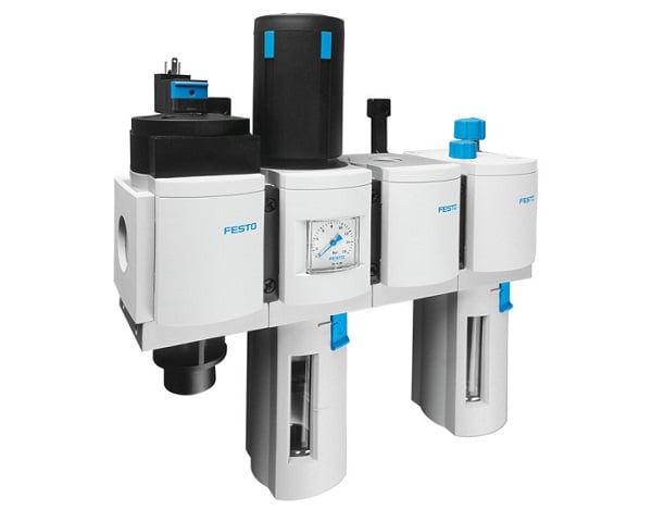
Figure 1. Festo’s MS series air preparation service unit. Image used courtesy of Festo
The Shut-Off And Regulator
At a bare minimum, equipment that lives downstream of an air compressor must be protected with a shut-off valve and a regulator. These components allow for the system to be de-energized of incoming stored energy, (compressed air) and to control the amount of pressure being fed into the system.
A shut-off valve is a fairly obvious on/off switch, often including a feature to allow operators to attach a lock and tag for safety purposes. When locked out, the valve will not be able to actuate back into the open position.
The primary function of the valve is to remove the connection to the air supply when the valve is shut off. In some cases, a valve is outfitted with a pressure relief function to bleed the residual air out of the system. If this is not included, an external pressure relief must be used downstream of the shut-off valve.
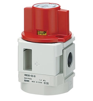
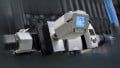
Figure 2. Shut-off valve with a lock-out and pressure relief features. Image used courtesy of SMC
The regulator is a device that controls the amount of air pressure entering the system. The air pressure inside the compressor tank is often much higher to accommodate pressure drops from long runs of pipes and tubes. All devices within a system have a maximum pressure rating; if the pressure exceeds the maximum, the device could be damaged.
These two devices will often be connected together. Maintaining these devices is simply actuating them once a month to make sure they are still functional.
The Filter
Pneumatic valves and components often use very small orifices that could be clogged or even damaged if small particles enter the compressed air system. The same can be true with moisture. Compressing air generates moisture, and if that were to enter a valve bank, the valves could be damaged by rust.
The job of the filter is to remove particles that could clog downstream components. Different-sized filters can be chosen depending on the requirements of your devices. Some sensors or industries (food/bev and medicine, for example) are particularly sensitive to foreign contamination debris, requiring a finer filter in the FLR unit. A standard filter size would be 5 or 10 µm, while a fine filter might be 1 µm or smaller. As the filter becomes finer, the flow rate through the filter will degrade, so the physical size (surface area) of the filter element becomes quite large.
When choosing a filter, refer to the manual of your devices to find the recommended filter. If you have only one device that requires a fine filter, you could add a filter just upstream of that device without restricting the entire system.
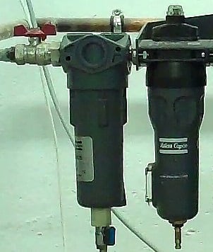
Figure 3. Pneumatic filter and moisture trap. Image used courtesy of Wikipedia
The filter typically has a second job which is to remove moisture from the air. By using a centrifugal force, moisture within the compressed air is forced out and will be deposited at the bottom of the filter. On a regular basis, when the filter becomes filled with moisture, it must be emptied via a small valve at the bottom of the filter.
The Lubricator
Most pneumatic cylinders, valves, and air knives today are self-lubricating and do not require lubrication in the air supply, but some pneumatic devices still require this lubrication, such as air motors, hand tools, and some old ‘packed’ cylinders and valves. If your components do not require lubricated air, then the lubricator can be removed from the air preparation unit.
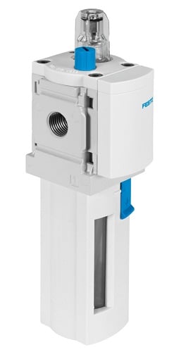
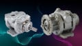
Figure 4. Festo air line lubricator from the MS series. Image used courtesy of Festo
An air lubricator siphons oil from a reservoir and atomizes the oil into the air, resulting in a lubricated air supply, but not enough to create a flow of liquid oil and restrict the airflow.
These units will need to be refilled with oil frequently and the units will need to be checked for leaks weekly.
Electronic Dump Valve
The last component in your air preparation unit will be the electronic dump or residual pressure release valve. This is an on/off valve that is controlled by an electric signal, typically 24 V from a control system. Most automation equipment built today will require a category 2 or higher dump valve controlled by a safety PLC or safety relay. When the signal is off, the valve closes, and the system pressure will vent to the atmosphere, releasing the stored energy.
When pressure is meant to be restored, a common soft-start feature allows pressure to build gradually until 100% system pressure is achieved. Using this soft start, devices are not subjected to the immediate shock of full pressure when the valve is opened.
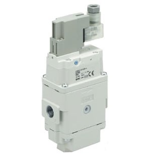
Figure 5. Electronic dump valve with soft start. Image used courtesy of SMC
A feedback device is often attached to ensure the air pressure has indeed been vented completely. After the electronic dump valve, you can attach branching modules that allow for pipe or tube connections that will connect to your downstream devices, such as valve banks.
The Completed Air Prep Assembly
Once you have determined which components you need in your air preparation unit, you will need to know the amount of flow through the devices. Each device within the preparation unit has a size rating which refers to the amount of airflow possible through the device and its native pressure drop according to the airflow rate.
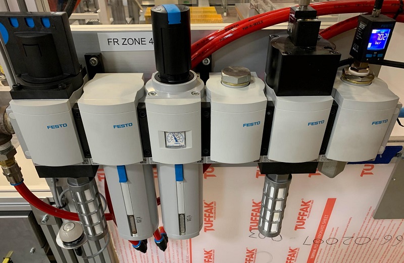
Figure 6. A completed pneumatic preparation unit in action. Image used courtesy of the author
As an example of a complete unit, Festo sells a combination service unit across five sizes: MS2, MS4, MS6, MS9, and MS12, ranging in flow from 350 L/min to 22,000 L/min. Some manufacturers sell all of the components separately and it’s up to the purchaser to ensure all the flows and ports match.
The air preparation unit is an important piece of equipment that prepares the air before it enters the components downstream and houses internal safety features that help keep operators and maintenance staff safe on the job.
Related Content