Facebook
 Google
 GitHub
 Linkedin
Tutorial: Design a Temperature Controller Using Node-RED
Not every control system requires an expensive PLC. This tutorial will introduce Node-RED, a popular programming environment that can be installed on a low-cost single-board controller.
Ever wanted to build a project on that Raspberry Pi you have sitting around, but you don’t know anything about Linux or Python? Now is your chance. Follow along as I build a temperature controller using Node-RED and a Raspberry Pi.
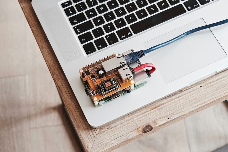
Figure 1. A Raspberry Pi being used in a home automation project similar to the one described in this article. Image used courtesy of Unsplash
Controlling The Temperature
The temperature controller project is a common lab exercise for control engineers who are just starting in the industry, because it involves analog sensors, digital outputs, and some logic to tie it all together.
Similar to a standard electric stovetop, we will read the temperature of our environment and set an output when the temperature exceeds a value set by the user. For this project, I will be using a Raspberry Pi, a DS18B20 temperature sensor, and the Node-RED programming environment.
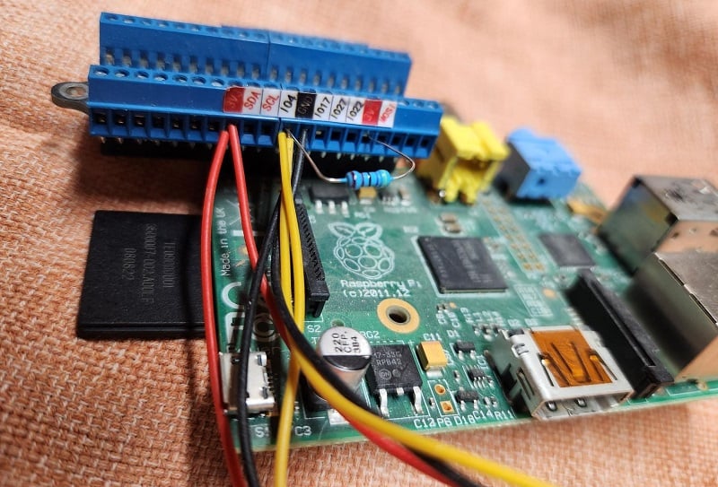
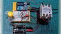
Figure 2. Image of the Raspberry Pi wired with temperature sensors. Image used courtesy of the author
Sensing Temperature With The DS18B20
There are a few ways to measure temperature; RTDs and thermocouples are the most common, but these sensors require amplifiers or signal conditioners. One of the benefits of the DS18B20 is that it is digital, meaning it doesn’t need an amplifier or signal conditioner.
The temperature is sent using the 1-Wire communication technology, meaning that only one wire needs to be connected to the controller inputs for the sensor signal, regardless of the number of sensors connected. This is more space-efficient than either SPI or I2C, other common serial protocols.
Wiring The Sensor
The wiring is simple but will require a 4.7kohm resistor. Vcc and Gnd are wired to 5VDC and ground, respectively, with the SIG wire going to an empty input on one of the GPIO pins. The resistor will be connected to power and the signal wire. Each sensor will be connected the same way, and to the same input.
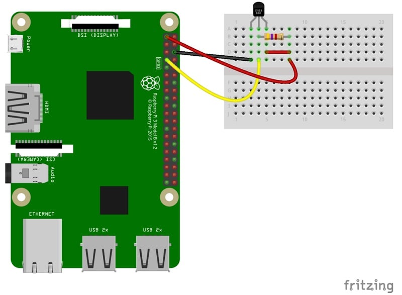
Figure 3. Wiring example of a DS18B20 temperature sensor. Image used courtesy of Wikipedia
Installing The Software
I’m using Node-RED for the programming interface to show how easy it is to communicate with an input device, write logic, and deploy to your hardware. The installation of the Node-RED software is just as easy. Detailed instructions can be found at nodered.org. After installation, there are a couple of nodes that must be installed via the palette manager.
To communicate with the temperature sensor, I prefer to use the node-red-contrib-sensor-ds18b20 node as it proved the simplest to integrate. The other nodes you will want to install are node-red-node-pi-gpio nodes. These nodes will allow you to interact with the Raspberry Pi hardware. You may have been prompted about these nodes during installation. Once all the software is installed, we can begin the programming by opening up a browser and navigating to http://localhost:1880.
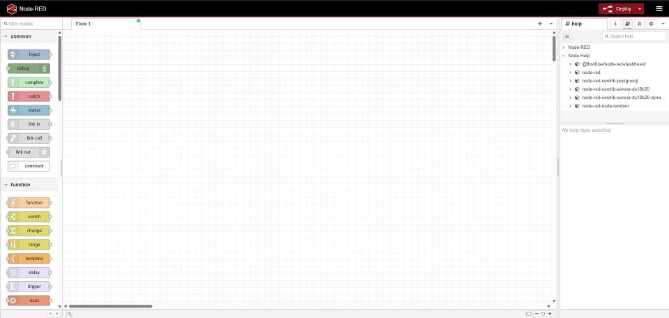
Figure 4. The Node-RED programming interface. Image used courtesy of the author
Programming the Temperature Controller
I like to start with the inputs when programming, so I’ll add my ds18B20 node to the flow. The properties of the node will allow you to select which sensor you want to read. If there are no sensors listed, ensure your wiring is correct before continuing. You will also need to set a periodic rate; otherwise, the node could reduce your Pi’s performance with excessive processing. Drag and drop a debug node onto your flow and wire it to the sensor node. This will allow you to see the temperature live in your debug window.
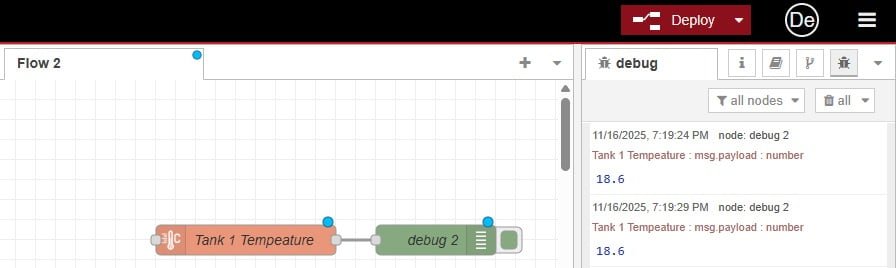
Figure 5. Reading the temperature from the sensor into the Raspberry Pi. Image used courtesy of the author
Don’t forget to click Deploy at the top menu bar each time you make a change; this will deploy your changes for you.
Now that we are reading the temperature, we can apply some logic. Using the switch node, we can create an if statement that will output the payload if our temperature is greater than some value. Again, use the debug node to test if the switch node is working as expected. To ensure we turn off the output when the switch statement is not true, we will need to add a rule and check for less than the set value.
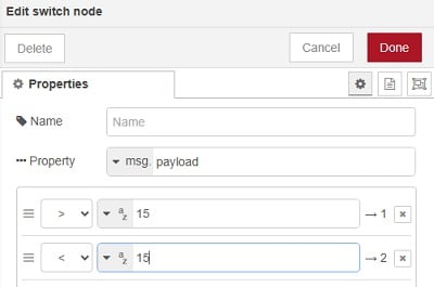
Figure 6. Switch node properties to output a payload if the temperature is greater than or less than a value. Image used courtesy of the author
The GPIO out node requires a payload of either 0 or 1, so we need to change the payload depending on whether the switch node results in greater than or less than. We use two change nodes to set the value of the payload to either 1 or 0, and wire them to the two outputs of the switch node.
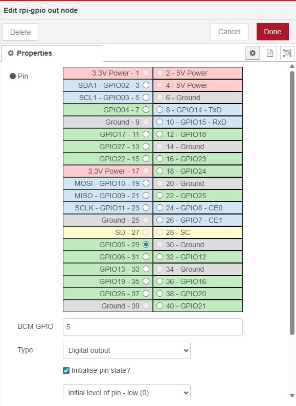
Figure 7. Setting the GPIO output properties. Image used courtesy of the author
Now we are ready to send the output to our GPIO pin using the Raspberry Pi output node. We simply drag and drop the output node onto the flow and connect both change nodes to the one output node. The properties allow us to select the pin we want to use for our output.
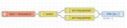
Figure 8. The entire program for controlling an output based on a setpoint and a temperature sensor. Image used courtesy of the author
Now, when the temperature is above the value we used in the switch node, the upper change node will set the payload to 1, and the output node will set pin 29 to output 5VDC. When the temperature drops below the switch value, the lower change node will set the payload to 0, resulting in setting pin 29 to low, or no voltage.
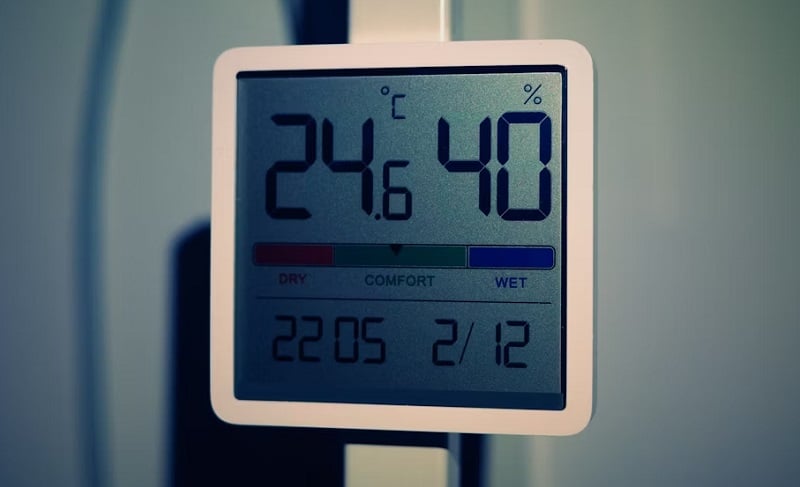
Figure 9. A temperature control dashboard that could easily be replicated on Node-RED. Image used courtesy of Unsplash
Easy As That
With five nodes and 10 minutes, we created a temperature controller. This is a very simple representation that gives you a glimpse of how easy the Node-RED interface is to interact with. We could add further processing to prevent short cycling of our output by adding a filter node and or increasing our periodic value in the sensor node. We can take this even further and add a database connection or even a dashboard to change the setpoint and view the temperature from any device on our network.
As the industry of low-code filters down into more industrial automation devices, we will likely see programming interfaces such as Node-RED used in industrial settings, so for your next DIY or industrial automation project, have a look at a low-code solution such as Node-RED.