Facebook
 Google
 GitHub
 Linkedin
Understanding LiDAR Technology in Industrial Applications
Learn about LiDAR technology and some of its basic concepts of operation.
LiDAR is a technology that was first conceived in the 1960s, primarily for military purposes. The first sensors, informally known as “Light and Radar,” were mounted on airplanes and helped map terrain and track military targets.
LiDAR technology advancements then stalled. Until the early 1990s, the integration of the Global Positioning System (GPS) into survey processes brought about a new era where more industries benefitted from increased precision levels.

Fig. 1. The LiDAR scanner in an iPhone 12 can be used for Measurements and 3D Imaging. Image used courtesy of Apple
For the last several years, LiDAR has experienced a new boom in advancements and industry adoption. From autonomous cars to smartphones and sensors mounted on drones, LiDAR has changed from once dormant to a unique technology market.
How Does LiDAR Technology Work?
LiDAR stands for “Light Detection and Ranging.” The basic operating principle behind a LiDAR sensor is that a laser beam is aimed at a target, and the distance to that target is calculated by measuring the time for the beam to reflect the source.
In most sensors, the light at wavelengths invisible to the human eye is used, such as infrared or ultraviolet. The LiDAR sensor emits a light beam at a generally fast speed.
For example, for rotating sensors, the scanning frequency can be between 200 and 900 rpm. It can be even higher than 900 rpm in safety-rated devices and sensors used outdoors and require high precision regardless of conditions.
Some applications require the detection of special retro-reflective landmarks, most modern LiDAR sensors are capable of measuring the distance to any surface. In many applications, the sensor must read through gases or other particles in the air, such as fog or dust. The ability to discern between a true object of interest of a survey and an element that needs to be filtered out also lies in the post-processing of the data output by the LiDAR device.
Point Cloud Analysis
What does the data generated by a LiDAR sensor look like? The laser scans are recorded in a collection of many discrete points, known as a point cloud. Each point has attributes of location (X, Y, Z) and intensity.
By knowing these attributes, a person can later classify each point as representing a different object or material (terrain, machinery, vegetation, etc.). This highlights one important limitation of the LiDAR technology.

Fig. 2. A LiDAR point cloud generated in an aerial survey of the city of Pittsburgh. Image used courtesy of the U.S. Department of the Interior
Laser scans cannot autonomously distinguish between different types of objects. The laser measures the distances to the first obstacles encountered in its line-of-sight, regardless of what those obstacles are. Despite this, point clouds provide tremendously valuable information needed in systems where precise measurements, positioning, and distances are required.
Computing Power Requirements
LiDAR sensors need to be integrated with strong computing and graphics processing units to handle large amounts of data in a point cloud. In many applications, several point clouds are analyzed simultaneously, resulting in even larger data sets.
For this reason, some LiDAR devices are equipped with state-of-the-art Transputer Processing Units (TPUs). As an alternative to conventional CPU design, a transputer offers greater parallelism in the architecture.
First introduced in the 1980s, transputers are reemerging as both a hardware piece and a key design philosophy. This is due, in part, to the traditional supercomputer design trends reaching limitations of power consumption and heat dissipation.

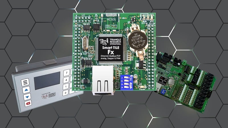
Fig. 3. The NAV350, a 2D LiDAR from SICK is equipped with a TPU. Image used courtesy of SICK
A LiDAR’s TPU can analyze the raw point data and produce outputs and results of the analysis in a simplified form.
For example, the position of a target object, the speed of that target, object counts, mathematical trends, among others. This is the classical architecture used in industrial automation. The complex point clouds evaluation is left to the LiDAR device and its TPU, and only relevant outputs are sent to the PLC or main controller.
For instance, in an autonomous mobile robot (AMR), LiDAR-based safety sensors are usually mounted. These sensors evaluate point clouds to determine if an obstruction is detected. Then, the sensor’s TPU compares the obstruction represented in the point cloud against preconfigured “safety fields” or detection areas.
If the obstacle detected infringes the safety field, the sensor sends an output to the safety PLC and instructs the vehicle to stop. All the safety controller receives is a single bit or signal that resulted from the analysis done by the LiDAR device.

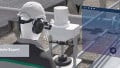
Fig. 4. An array of LiDAR-based safety scanners communicating with the safety controller of an AMR. Image used courtesy of SICK
With a wide array of applications, LiDAR sensors have quickly become a key technology in autonomous vehicles, drone-based inspections, smartphones, spec, industrial automation.
Related Content