Facebook
 Google
 GitHub
 Linkedin
Using the Allen-Bradley Ramp/Soak Controller With a PID
This article will focus on using an Allen-Bradley ramp/soak controller with a PID.
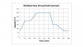
A previous article on the Introduction to the Ramp/Soak Controller discusses the definition and history of a ramp/soak controller.
This article will provide a specific example of a ramps/soak controller being used. If you'd like to review more basic concepts before continuing, please refer to the previous article linked above.
Allen-Bradley does not have a built-in ramp feature in their PID or even their PIDE (enhanced PID) instruction. Perhaps this will change in the future, but until then, adding the ramp/soak (RMPS) instruction as the cascade setpoint to the Allen-Bradley PID or PIDE instruction will provide setpoint ramping as well as some very powerful additional features.
Using the Controller with a PID
The ramp/soak instruction (known as RMPS within the Allen-Bradley PLC) is typically used to control the setpoint of a PID or PIDE (enhanced) instruction. This can be accomplished by connecting the output of the RMPS instruction to one of the setpoint inputs of the PIDE instruction. I will only refer to the PIDE instruction from here forward.
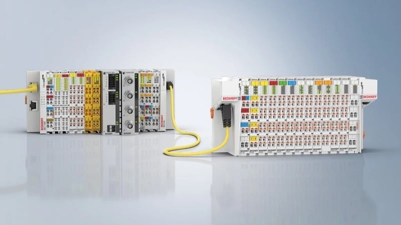
A typical implementation of the ramp/soak with a PIDE in the Allen-Bradley Compactlogix controller. View this image here. Image used courtesy of Rockwell Automation.
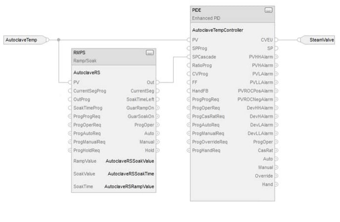
In the example below, the RMPS instruction output (Out) is connected to the PIDE cascade setpoint (SPCascade). In this configuration, the PIDE can still be used without the ramp/soak, or with the ramp/soak when in cascade mode.
To store the ramp/soak steps, three REAL (data type) arrays are needed to store the ramp time/rate (RampValue), soak value (SoakValue) and soak time (SoakTime) for each step.
To use the ramp/soak feature in the RMPS instruction, the operator needs only to enter a few parameters to set up the ramp/soak profile such as; the number of steps, ramp time for each step, soak value for each step, and soak time for each step. Once these parameters are entered, the RMPS is initialized and placed in manual. The PIDE loop with the RMPS instruction connected to the cascade setpoint is then put in “Cascade”, the RMPS placed in “Auto” and the ramps/soak profile is started.
A Non-Traditional Use of the Ramp/Soak Controller
In a recent application, I included the RMPS instruction with each PID loop on the project as a standard feature for the operators to use. It wasn’t long before I was getting some unusual requests from our operations personnel for using the ramp/soak in our application.
In this application, a small 20 mL reactor that contained a catalyst was fed with flows from up to eight different flow loops.
The reactor temperature was controlled by two temperature loops and the pressure in the reactor was controlled by a back pressure control loop. The operators ran tests on the catalyst using criteria provided by research scientists working closely with them.
A typical test would involve manipulating the incoming flows for predetermined durations with the reactor at a given pressure and temperature. This was all done by the operator diligently monitoring the system and adjusting the setpoints at the given time as required by the test plan.
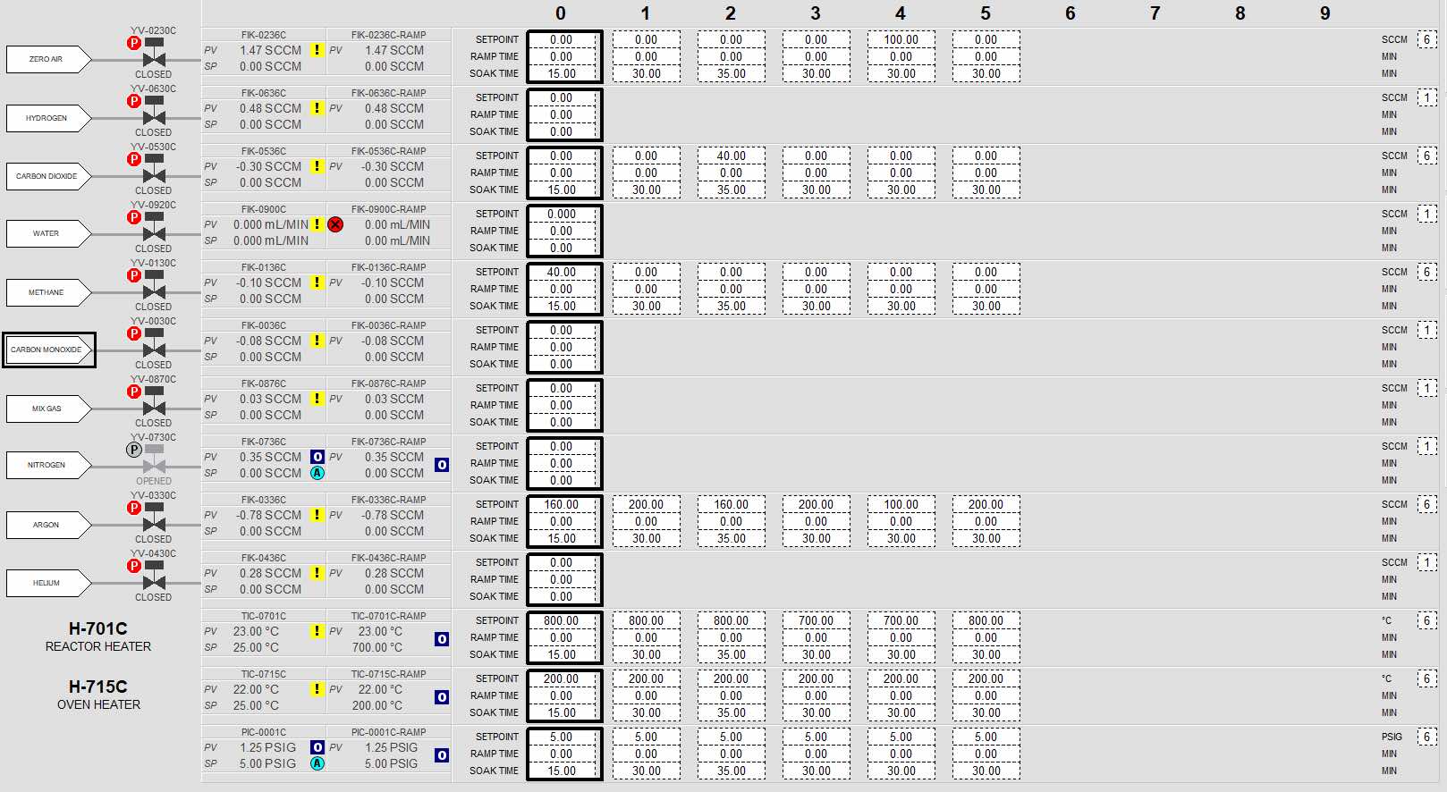
A (somewhat daunting) but comprehensive ramp/soak control screen for a catalyst test facility. View the full image here.
I was asked if the system could be programmed to automatically adjust the setpoints for each of the different test plans and have the tests run automatically with the operator having to monitor the system constantly.
I had added the ramp/soak controller to the flow loops primarily for the setpoint ramping feature, but soon realized that the operators could program all the required flows, temperature, and pressure setpoints along with ramp and soak times into the ramp/soak controllers and have the system run the tests automatically.
All that was needed was a comprehensive interface where the operator could see all the ramp/soak setpoints in one place to help them layout the test plan. Below is a screenshot of the somewhat daunting control screen I came up with for the task.
Benefits of Using a Ramp/Soak Controller
In this application, the ramp/soak controllers work in concert across multiple control loops and somewhat resemble the operation of a sequencer but without the programming to go along with a sequencer.
The system is very flexible and has even allowed the tests to be conducted overnight and unattended. This allows the researchers to gather their data in less time as they can run multiple eight-hour tests a day instead of just one during the operator’s shift.
The RMPS instruction that is included in the Allen-Bradley PLCs is flexible enough to provide both the basic essential functions of a ramp/soak controller as well as some advanced functions that you would normally see in such a controller.
I consistently add the RMPS instruction to all of the PID loops that I program as an additional feature that operators have now come to expect as a standard part of the control loop.
Have you used a ramp/soak controller before? If so, let us know how in the comments.
Related Content