 Facebook
 Google
 GitHub
 Linkedin
Industrial Robots
By far the largest market share of robots of any kind in the current world is industrial robots. These are differentiated from other robot platforms by having both a fixed, immobile base, as well as a high speed allowance with fewer collision checks. When either of these conditions are deviated, either by making the robot mobile or by adding safe, collaborative speed limits and collision features, the type of robot fundamentally changes.
Industrial robot product lines typically have the highest payload capacities, work envelope ranges, and speeds available for robots, but even within the industrial robot world, there are various configurations of motion axes which lend themselves better in certain situations.
Common applications of industrial robots include:
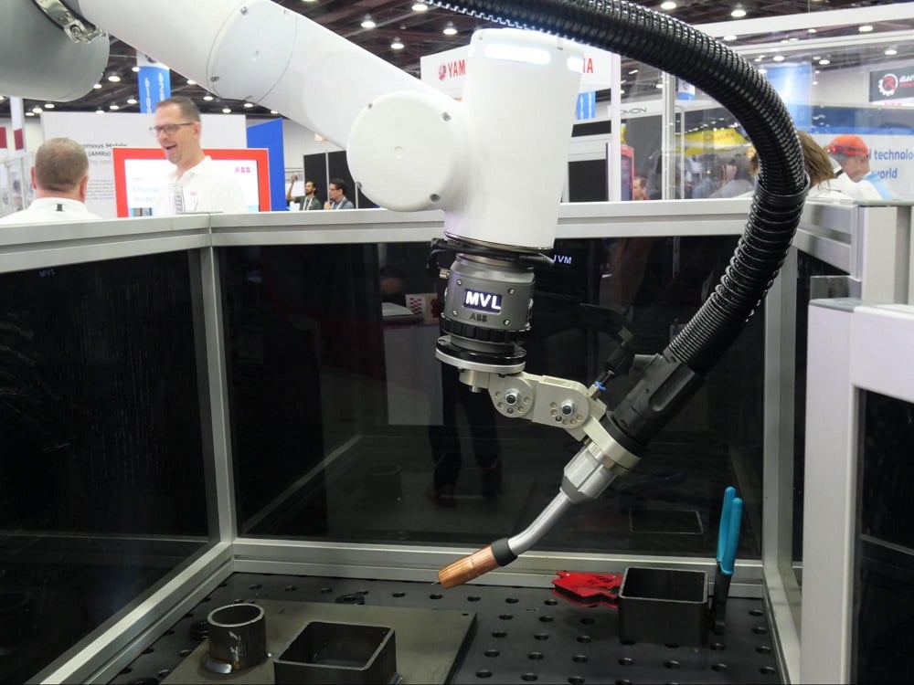
- Welding
- Painting
- Pick and Place of nearly any sized object (from tiny SMD electrical parts to full-size cars)
- Palletizing, which is a subset of pick and place
- CNC machine loading/unloading
What are Industrial Robots?
Perhaps the simplest way to define a robot is any combination of motion axes, either linear or rotational, which move some sort of end effector, commonly known as an ‘end of arm tool’, to accomplish a task automatically.
This somewhat vague definition means that nearly any combination of sliding, moving, rotating motors that hold things could be considered a ‘robot’ and this is correct. However, nearly all of the endless configurations can usually be condensed down into just a few more specific categories, to include the following:
- Articulated arms
- SCARA
- Cartesian (also gantry or linear)
- Delta
The very first industrial robot was developed in 1961, used by General Motors, and was called Unimate. It was used to move and weld die-casted parts, which means that the very first applications for robots were indeed welding and pick-and-place.
In the 60+ years that have followed since the invention of the first robot, devices have become lighter, stronger, and much, much faster. The most recent developmental trends in the field of robotics, beyond simply increasing the accuracy and specs of the systems, are the desire to make robots easier to program without extensive knowledge of structured text coding, and the ability to connect them to peripheral systems with greater ease.
Articulated Arm, or 6 Axis Robot Arm
These are the devices that will most often be referenced by the number of rotating joins, commonly between 4 and 6-axes. Fewer axes results in greater payload capacities, but decreased range of tool motion.
A 4-axis industrial robot arm is unable to swivel the gripper to all positions, and is ideally suited for moving payloads that are always alighted with the ground, or the horizontal plane. The base of the robot on this horizontal plane is identified by the X-Y plane, so the payloads on these 4-axis robots are able to move linearly along the Z-axis, but not rotate around it.
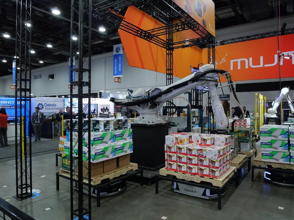
We often find these robots loading and unloading pallets, since the infeed and outfeed conveyors, and the pallet, are all arranged around the robot, but level with the ground. The reduction in axes results in easier jogging/teaching procedures, decreased ongoing maintenance and failure points, and lower power consumption.
For more complex manipulative tasks, such as welding and painting, where hand control around corners and over angled surfaces is required, the 4-axis robot simply is not sufficient. A 5th or 6th axis allows freedom of motion for the end tool nearly anywhere within the work envelope of the robot.
Work Envelope
Each variety of robot is defined by the entire possible area throughout which the end tool can move. They are assigned geometric shapes to give a physical perspective of motion to novice programmers. With more experience, you no longer need to image the shape, as it becomes easier to simply visualize the robot in the target configuration.
Spherical Work Envelope
A typical articulated arm has a spherical work envelope. It should be emphasized that although it might be theoretically possible to move the robot through this complete sphere, it would obviously collide with its own base if it were to try and move straight down into the floor (for a floor-mounted model). However, if it is ceiling mounted, the reachable target locations change. So there is always a difference between the theoretical work envelope and the actual, practical motion afforded by the installation.

The end tool will also affect the range and work envelope. When a robot spec sheet is provided, the range and reach only account for the factory default configuration. This accounts for no end tools, and the tool center point (TCP) is considered to be the center of the flat face onto which any end tool is bolted. Any tool will adjust the actual center point and must be carefully input into the controller. This will be discussed more in a later section.
Robot Arms: Accuracy, Repeatability, and Resolution
These three terms are used quite often in any scientific field in the context of data and measurements. For robotic motion, these measurements are critical, and even a small percentage error can mean the difference between success and absolute failure of quality control.
Accuracy
Accuracy is the ability of a process to land directly on a point that it was supposed to reach. In the case of a robot, this is a point located in 3D space, an x-y-z coordinate. If the robot is supposed to reach the point, but the accuracy of the encoders is limited, it might land directly on the point one time, but then might be +/- 1 or 2 mm away the next time. Since it’s inconsistent, this metric is often included in the statistic of repeatability, so a robot manufacturer may not include the accuracy of the arm, only the resolution and repeatability.
Repeatability
Landing directly on a point is critical for any robotic process, but it’s most important when the objects to be manipulated are very small.
If the robot is meant to grasp a 1’x1’x1’ box and place it on a pallet using spring-loaded vacuum grippers from above, a small offset of ¼” on each box may not be that worrisome, since the plastic shrinkwrap process will tighten the stack later.
On the other hand, if the robot is selecting and placing the correct 0805 form factor surface mount (SMD) ICs, the smallest edge dimension is only 0.05”. That same assumption of ¼” offset would be absolutely unacceptable.
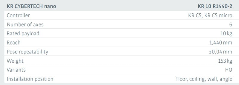
Repeatability is a statistic, usually measured in mm or in inches, which defines how close the robot will be able to come to landing on the same point over and over. It is not uncommon to see small fractions of mm repeatability. The image above is an excerpt from the datasheet for Kuka’s Cybertech Nano industrial arm series with a repeatability of 0.04 mm! In this statistic, the smaller the number, the more accuracy the robot will achieve.
Resolution, or Precision
When jogging a robot to teach the proper points, there are various speeds that can be used. Rapid speeds allow transverse over a long distance, like from an infeed to outfeed conveyor. As the final point is approached, the speed is set lower and lower until finally, the lowest possible speed is set. A single button press will move the robot the smallest possible distance interval.
Imagine if a robot could repeat the same point down to 0.05 mm, but the smallest jog distance possible was only 0.5 mm. The poorer resolution of the move negates the excellent repeatability. Therefore, the resolution of the robot must be a smaller distance measurement than the repeatability of the robot for both of these measurements to be significant.
Since the placement of the robot gripper is the single most important attribute of a robot, some manufacturer spec sheets will only list the repeatability of the robot.
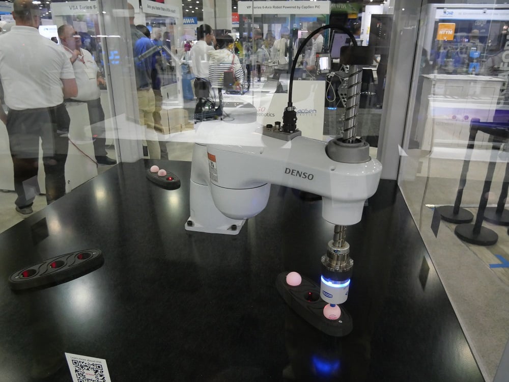
SCARA Robot
The term SCARA refers to ‘selective compliance articulated robot arm’. Although it is articulated, it is usually not referred to as a ‘robot arm’, which is generally reserved for the 4-6 axis models.
Cylindrical Work Envelope
The SCARA platform consists of a fixed base around which one joint revolves, usually with 360 degrees or more of motion. Attached to this joint, at a short distance from the central axis, is a second revolving joint. Finally, a further distance down this second joint is a linear axis, allowing the gripper to move vertically in the Z-axis direction.
The robot itself then consists of two revolving axes and a single linear axis. Unlike its cousin, the articulated arm, which can navigate within a spherical envelope, the SCARA is limited to a cylindrical work area.
SCARA Robot Speed
The gripper of the robot may contain additional motion axes, often a 4th axis designed to rotate the workpiece. Without this final axis, the rotation of the base and shoulder joints would dictate the position of the part when it is placed at the drop point, which may be undesirable. Adding this 4th axis allows the part to be oriented completely independently of the other axes.
With its highly specialized design and fewer axes, as well as the shorter reach compared to most articulated arms, the speed of SCARA robots is higher. They are well-suited for high-speed picking and placing of small objects, and are often found in the medical and pharmaceutical industries, and where sorting small objects at high speed is necessary. Paired with a color vision system, this kind of robot could sort a bag of candy by color faster than the eye could follow.
Vibration Damping
With increased speed comes the risk of overshoot and vibration. A higher speed rating on a robot is of no value if it must pause briefly at the final location in order to settle and stop shaking. Robot designers recognize this flaw, and must compensate with higher vibration damping and responsive control systems in order to achieve greater speeds.
This damping can be accomplished in two ways, either be open-loop or closed-loop control.
With open-loop damping, the payload must be known at all times. In most programs, a ‘payload schedule’ determines when the gripper will be empty, and when it will have one of the payload parts attached, which could be one of several possible. The open-loop control system analyzes the motion speed and distance, along with the payload schedule and is able to predict exactly how fast to accelerate and decelerate to achieve maximum accuracy at the highest possible speed.
This system cannot, however, compensate for any other variables such as the flexibility of the base (if it’s mounted on a semi-rigid table, for example). Open loop systems can only factor in the known variables of the system itself, which, under ideal operating circumstances like solid mounting, exactly calculated payloads, etc., can be very reliable.
Closed-loop control can compensate for many unpredictable factors, at the risk of a more complex control system and extra sensing hardware. For robotic systems, the sensor is likely to be a multi-axis accelerometer and gyroscope embedded as close to the workpiece as possible. This extra sensing can inform the controller exactly how fast the payload is moving, including intended motion from outside factors, allowing PID algorithms in the robot to begin decelerating or changing motion with different profiles.
Closed-loop control is far more reliable for any process. The downsides presented by additional hardware and wiring, as well as programming, are becoming less burdensome daily as technology advances. As robot control systems advance, it is likely that fewer systems will rely on open-loop control, where we must hope only for ideal working conditions to achieve precise motion paths.
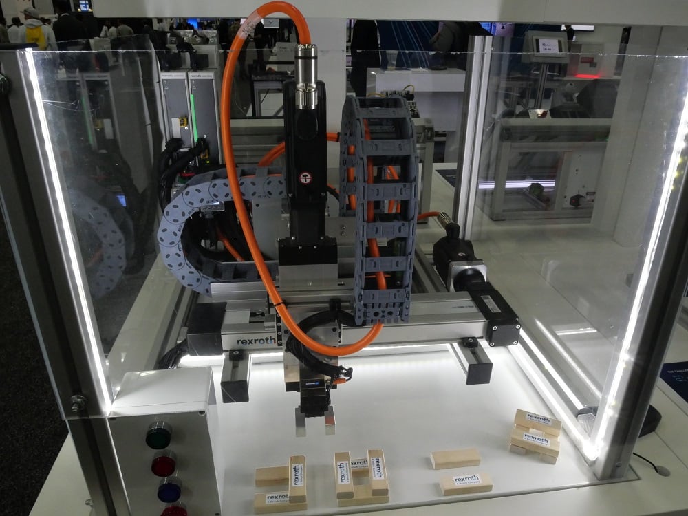
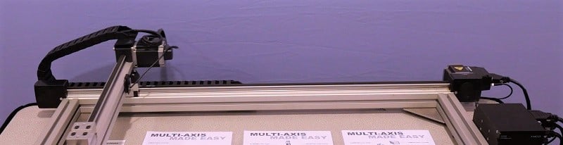
Cartesian (Also Gantry or Linear) Robots
Both of the previously presented robots contain rotational axes, but these are limited in the maximum reach of the tool. If a long span of motion is required, the often-used model is a combination of long linear beams that serve as guides for straight-line motion.
These types of robots might sometimes go by other names, like a CNC table used for lasers, waterjet, or plasma cutting, so we might not immediately recognize these as a robot. Regardless of the name, these combinations of axes move a tool to accomplish a task and are, therefore, robots indeed.
Three main modes of power transfer are used for these long, linear axes.
First is the toothed rubber timing belt. A motorized sprocket at one end of the axis turns the belt, and with the proper tension, moves a carriage along the beam. For stability, the carriage is attached with rollers that glide along grooved beams of metal. Larger carriages will contains more durable, solid bearings.
For long spans, the belt must be properly tensioned with springs or idler pulleys, and will usually be much thicker for durability. For shorter spans, the belt is pulled to hand-tight then secured with a small screw-down plate. Unless subjected to abnormal force, it will not need any further adjustment.
The second common power transfer mode is the ball or lead screw. A threaded shaft, much like any normal screw, is rotated by a motor. The carriage mechanism, which resembles a threaded nut, is moved axially along the shaft as the motor rotates. This method is excellent for control, and, much like a worm gear, is nearly immune to backlash. With a minor reverse force applied to the payload, the ball screws will prevent it from easily driving back against the motor.
Long spans can be difficult for ball screws. The weight of the metal shaft will cause it to sag, and as the motor spins, harmonics can develop along the length, causing vibration and damage to the carriage and its bearings. This method is very common for short CNC machine axes, but less common for spans longer than just a few feet or meters.
The final power transmission for long linear axes is a rack-and-pinion gear method. The moving carriage is outfitted with a single motorized spur or helix gear, meshed to a single long row of matching teeth along the entire length of the axis. An advantage to this method is that the axis can be infinitely long with no additional sag, stretch, or droop that are introduced with the other methods.
Gears can also provide more control over travel speed. Changing the driving pinion gear size, or attaching the motor to a gear train which is ultimately driving the pinion can multiply the precision of each step of the motor. In so doing, it might decrease the speed of rapid transverse, but gears are exceptional methods of creating precise motion in ways that timing belts and ball screws cannot.
Cartesian Work Envelope
These systems are called by the name cartesian because they naturally move only in an x, y, and z direction. The articulated arms are circular, so x-y-z coordinates must be calculated trigonometrically. Since humans measure distances linearly, the cartesian axes are easy to manipulate. Moving multiple axes at a time can recreate angles, arcs, and circles. Since they are designed with three linear axes, the work envelope for these robots is a rectangular prism.
Delta Robot, or Parallel Robot
Although these types of robots are fairly common, they remain a bit less visible to most of the engineering world. Like the SCARA robots, these can travel at extremely high speeds, but the range of motion is very limited.
Delta robots use a series of linkages attached to three motors placed in a wide triangular pattern at the fixed base (which is usually the top of the robot). These linkages, which may be up to a couple of feet long, are also attached to a much smaller triangular platform near the end of arm tool.

As the three motors at the top are rotated in synchronization, the small platform at the opposite end will be moved around the work envelope.
Several further axes can be attached directly at the platform, or the ‘wrist’ level of the robot, before the end tool is installed. These additional axes result in a 4 to 6-axis robot, so that the position of the tool is controlled by the three primary axes, but the angular orientation of the tool is controlled by these smaller axes at the end.
Cylindrical Work Envelope
The work area for these robots, much like for the SCARA, is a cylinder, largely dictated by the minimum and maximum extension of the three main axis joints. They are not designed to move very far, so the work envelope is relatively compact, but they can navigate at an extremely high speed.
Industrial Robot Installation
Since these robots are meant to run at high speeds without regard for obstacles which might occur in the motion path, it is critical to use them in a safe environment. Safety cages are installed around robots, consisting of a physical barrier to prevent entry unless the robot is placed into a slow ‘teaching’ mode of operation.
In some modern systems, virtual barriers are rated sufficiently to prevent entry into a work cell without the robot slowing down. These might even have ‘slow’ and ‘stop’ zones, so that the robot halts completely when someone enters the work envelope. An advantage of software-driven virtual barriers is an automatic restart at the point of pause once the person leaves the restricted area. With a physical emergency stop device, the program must be restarted from a safe point after the scene is cleared.
Industrial Robot Programming
Although it may seem a bit counter-intuitive, the biggest struggle with using industrial robots is often not the physical design and installation of the cell, but rather the programming and ongoing maintenance. This is most often because robot cells are designed by an OEM or integrator with a mature, experienced engineering department, but day-to-day problem solving must be handled by the end user.
Having some experience in the field of robot programming can greatly assist with both solving the problems, and facilitating the process when speaking with a helpdesk line that might need to ask technical questions to determine the root cause of the problem.
In the design, construction, and modification of robot programs, there are really only three categories of commands to learn. Become familiar with the categories, and the various parameters associated with each, and you might find that you can pick up any robot programming language with relative ease.
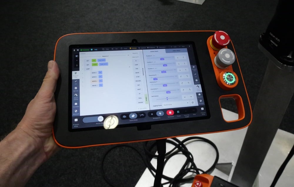
These three basic categories are motion commands, I/O commands, and program flow commands.
Robot Motion Commands
The objective of the robot is to move from point to point with no collisions, as quickly as possible and logical for the system. It stands to reason that even the simplest programs will consist of moving between points, so it is one of the most fundamantal command types in any language.
Two types of motions exist: absolute and relative.
Absolute Motion
Absolute motion is a directive to navigate directly to a specific x-y-z coordinate in 3D space, regardless of the starting point. Since all coordinate systems have an origin point, the robot itself must have a fixed universal coordinate system (UCS), usually located right at the center of the point where the robot bolts to the floor or pedestal. All motion is relative to that point, in both positive and negative directions specified by the manufacturer.
Some robots will have labels or stickers affixed to the outer casing near the base, providing a clear direction of the +x, +y, and +z directions. The coordinates of any point in the program can be estimated by looking at the base of the robot, then moving the correct number of mm, either in the positive or negative direction, for each of the three axes.
When dealing with absolute motion, the end location is always known, while the starting point may be different each time the command is called. Therefore, it is imperative that the robot have a clear path between the various starting points, and this known destination point, every time the command is called. Any obstacles in between will become collisions.
This kind of command is very helpful for set pickup and dropoff points, like a palletizer, or a pick-and-place application. Once you program a point once, you can call it as many times as needed.
Relative Motion, or Incremental Motion
For applications where the contour of a path is critical, such as a CNC cutter, or a sanding application, it may be useful to turn to relative, or incremental motion commands. With this motion model, it is now the starting point of the motion which is known, the final destination will change each time the command is called.
The term relative, in this context, means ‘relative to where we are right now’. When a command is called to move the robot, the command explains how far the robot should move along each axis, starting from its current location. Positive and negative no longer tell us where the robot will end up in relation to the fixed base, but where it will end relative to where it started.
The reason this incremental stepping of motion is useful for CNC machines is that the field used to design 2D and 3D parts are geometric combinations of steps along x, y, and z-axes. It is very easy for a machine to calculate how far it must move to draw a straight line of a particular length; this is exactly what relative motion accomplishes.
Likewise, it is very easy to perform some basic trigonometry and translate these steps into the absolute position by means of vector addition, so most CNC controllers can toggle between relative and absolute motion commands and position readout with the press of a button.
Attached to these basic coordinate instructions are usually a set of motion modifier commands. Connecting the dots from point A to B is only a part of the solution (albeit, a major part).
- Speed override is useful in final pickup and dropoff motions to approach the point slowly, while transporting across the wide area in between at a much higher speed. Each motion can be adjusted to its own custom velocity.
- Point termination provides an ability to use a point as a safe waypoint around obstacles, but not come to full momentary stop at the point. Coming to a stop adds cycle time and additional wear on the motion components.
- Motion offsets allow the programmer to use only one point over and over but adjust the final location by a known amount. For example, making a 3x3x3 stack of boxes. Only the first box location must be taught, then the program is offset in the x direction one box width, then another. Then, the y location is adjusted and the x pattern repeats, then again. Finally, the z is adjusted while the entire pattern repeats again until all 27 boxes are stacked, based off of one taught motion point.
Robot I/O Commands
Even the most simple robots are designed to complete a task. The attachment placed onto the end of the arm, the tool, must be activated periodically to complete the task. This is accomplished by some form of input and output signal.
There are usually other I/O points to connect to valves, relays, sensors, and external PLC I/O modules. In many modern cases, an advanced communication protocol like Ethernet, PROFINET, or an IO-Link connection could be used to transfer data between the robot controller and external equipment. These protocol channels are also set up as I/O registers to hold numeric or string text values to use in the code.
To activate outputs, the commands are often very simple, using a SET or RESET for boolean output addresses or by an assignment command (in the form of “variable_name = value;”). For discrete I/O terminals, the only possible values are HIGH and LOW, but for analog I/O or for registers from a communication channel, the values might relate to the size of a box, or a recipe value for a specific product batch, etc.
Using input values is a bit more complex, since they might be used to either drive a decision in the operation of the robot, or they might indicate a value used to determine a motion path. Most input usage methods can take two forms.
- IF statements are logical decisions based on the value of a register or an I/O. We might say ‘if the gripper is open, close it’, which would be a valid IF statement. We might receive the value of a product barcode, and IF the value fits a certain format, the box is placed on a certain outfeed conveyor. If many choices exist, the IF statement may take the form of a SWITCH/SELECT case, depending on the language.
- Assigning register values is a method of reading the input, maybe analog or from Ethernet, and placing the value into a storage register for use later in the program after the input value changes. These commands may take the form of ‘register_number = analog_input_address_1’
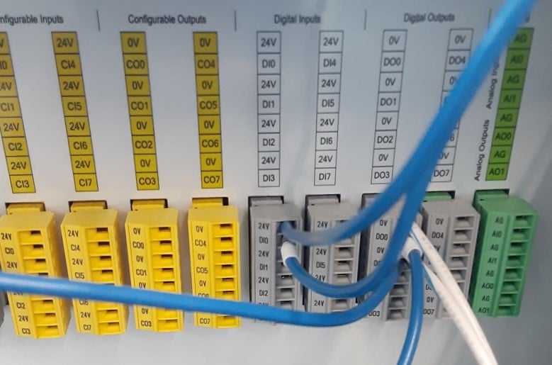
Most robots are equipped with three main I/O blocks - the local I/O screw terminals right inside the case of the controller (an example of which is shown in the image below with digital and analog terminals), network I/O located on removable, modular network interface cards, or hand I/O located somewhere on the arm itself near the attachment point of the gripper or tool. The commands are the same, but the addresses may be different for each location.
Program Flow Commands
Complex programs can be simplified by the use of creative navigation between the main routine and subroutines. Program flow commands can serve to jump, or ‘skip’, lines based on certain conditions or to exit the main program and execute a smaller section of code, much simpler to diagnose and troubleshoot. The conditions for program flow are very similar to the IF statements described above.
In addition to program flow, other very helpful commands include commenting for clarity and readability, assignment of various payloads (described in greater detail in the tooling section of the chapter), and assignment of coordinate systems (also called frames) which relate the points to the base coordinate system more conveniently for various tasks.
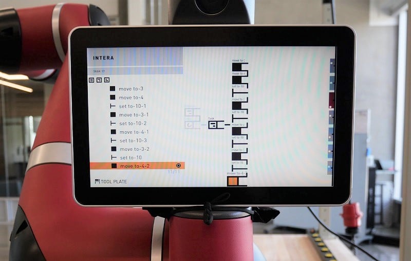
Human Robot Interaction
If the situation requires a human to work alongside a robot under normal operation, the traditional industrial robot is not a very good model. They are extremely fast and reliable, but the footprint required by the physical or virtual safety enclosure can be an expensive burden on the production line.
For situations like this which require collaboration between machines and humans, a recent development in collaborative robots has paved the way for faster programming and operation in thousands of applications.

Journals on Machine control using AI (machine learning, vision techniques) to do selections of materials and other machine functions