 Facebook
 Google
 GitHub
 Linkedin
Introduction to Modbus
Developed by the Modicon company (the original manufacturer of the Programmable Logic Controller, or PLC) in 1979 for use in its industrial control products, Modbus is a protocol designed specifically for exchanging process data between industrial control devices. The Modbus standard does not specify any details of physical networking, and thus may be deployed on many different types of physical networks. In other words, Modbus primarily falls within layer 7 of the OSI Reference Model (the so-called “Application Layer”) and therefore is compatible445 with any lower-level communication protocols including EIA/TIA-232, EIA/TIA-485, Ethernet (the latter via TCP/IP), and a special token-passing network also developed by Modicon called Modbus Plus. The Modbus standard primarily defines the meaning of various Modbus commands, the addressing scheme used to place data within devices, and the formatting of the data.
Modbus consists of a set of standardized digital codes intended to read data from and write data to industrial devices. A Modbus-compliant industrial device has been programmed to understand these codes and respond to them appropriately when received. The simplest Modbus codes read and write single bits of data in the device’s memory, for example the status of a PLC input channel, PLC output channel, or status bit within a PLC program. Other Modbus codes operate on 16-bit words of data, useful for reading and writing counter and timer accumulated values, operands for mathematical instructions, converted analog signals, etc.
Early implementations of Modbus used EIA/TIA-485 as the network physical layer, which is strictly a layer 1 protocol. This meant that Modbus needed to specify a channel arbitration scheme in order to negotiate communications with multiple devices on a network. The arbitration chosen was master/slave, where one PLC functioned as the master Modbus device and all other devices functioned as Modbus slaves.
Interestingly, this vestige of master/slave arbitration survives to this day, even when Modbus commands are communicated via networks with their own differing arbitration methods. For example, Modbus commands communicated over Ethernet still reference “slave” addresses even though the Ethernet network those messages are sent over uses CSMA/CD arbitration. In other words, there is a hint of OSI layer 2 embedded within Modbus messages that still dictates which Modbus devices may issue commands and which must obey commands.
Modbus overview
We may begin our exploration of Modbus by first considering an example of a PLC-controlled motor system that does not employ Modbus. Here, the PLC sends individually-wired Forward, Reverse, and Stop, and speed-control command signals to a variable-frequency drive (VFD) which then sends three-phase power of varying frequency to an electric motor to do some useful task:
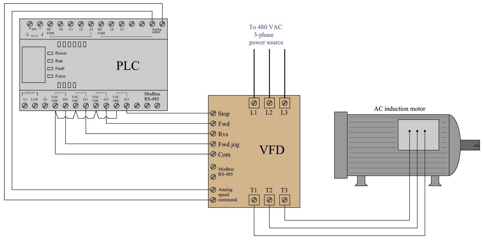
The discrete commands (e.g. Stop, Forward, Reverse) are nothing more than on/off contact closures provided by the PLC’s output channels to the VFD’s input terminals. When the PLC commands the VFD to run in the Reverse direction, it simply activates output channel O/1 which closes a relay contact inside the PLC to connect the VFD’s “Rvs” terminal to the VFD’s “Com” terminal. The VFD detects this electrical continuity, and responds by running the motor in its reverse direction. Motor speed is commanded by an analog voltage signal (typically 0 to 10 volts DC) output by the PLC, with 0 volts representing zero speed and 10 volts representing full speed. The VFD receives this analog voltage signal and responds to it by outputting the appropriate frequency of three-phase AC power to the induction motor.
While this system is certainly functional, it may be improved upon through the use of Modbus.
Now consider this updated motor control system, where the only connecting wires between the PLC and VFD is a single two-conductor cable between the Modbus/RS-485 terminals of both devices. The PLC functions as a Modbus master device while the VFD functions as a Modbus slave:
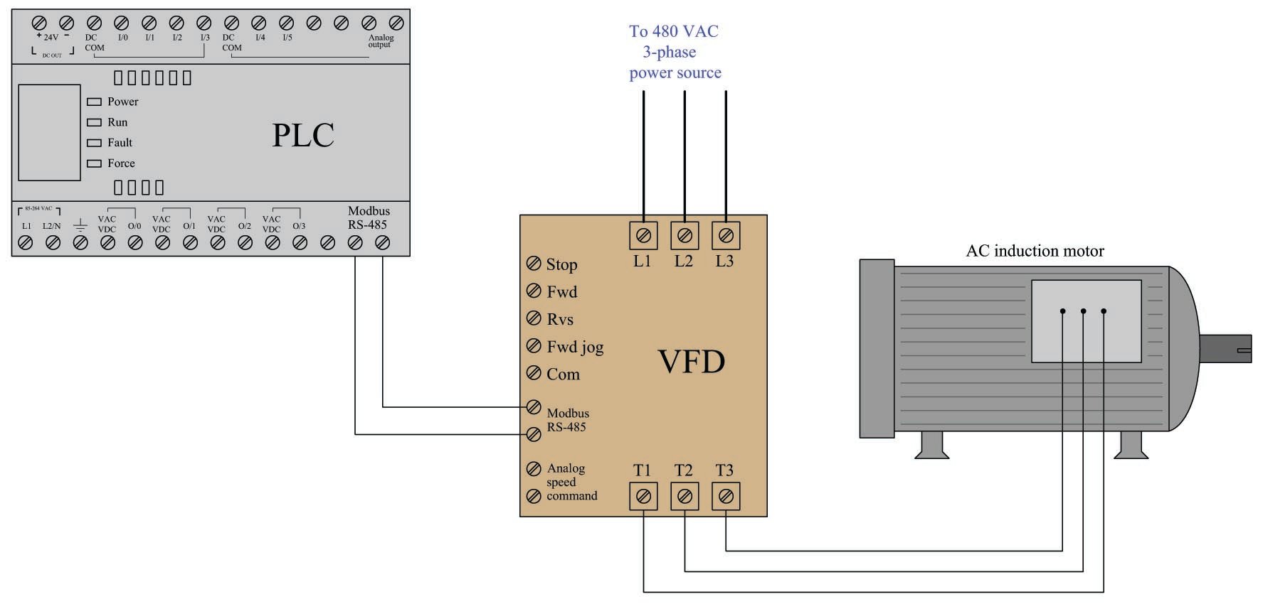
By using appropriate Modbus commands transmitted to the VFD, the PLC is able to issue all the same commands (e.g. Stop, Forward, Reverse, speed control) as before but using far fewer wires. For example Modbus command code 05 writes a single bit of data to the receiving device, allowing the PLC to send discrete-signal commands to the VFD one at a time. When the PLC commands the VFD to run in the Reverse direction, it issues a 05 command followed by a “1” data bit addressed to the appropriate memory location inside the VFD reserved for the “Reverse” command bit. When the PLC commands the VFD to change motor speed, it issues an 06 Modbus code (“write register”) followed by a 16-bit number representing the desired motor speed and the appropriate address within the VFD reserved for speed command.
Not only can the PLC issue all the same commands as before, but it may also read data from the VFD which it could not do before. For example, if the VFD provides a memory location for storing fault codes (e.g. motor overcurrent, bus undervoltage, etc.), the PLC may be programmed to issue an 03 Modbus code to read a single register (16 bit binary number) from that memory location within the VFD, and thereby monitor the status of the VFD to alert human technicians of potential problems, and/or to modify its own controlling of the motor.
Another advantage of the Modbus communication standard is that it is designed to address multiple devices on the same network. This means our hypothetical PLC is not limited to controlling and monitoring just one motor, but up to 247 separate Modbus slave devices on the same two-wire communication cable! The following illustration shows how this might work for multiple motors:
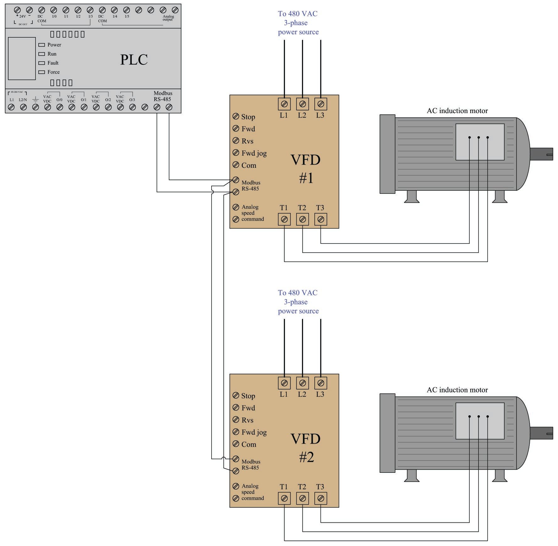
Each VFD is given its own Modbus network slave address, so that the PLC is able to distinguish between the two drives when communicating on the same wire pair. Every Modbus code transmitted by the PLC contains this address as a single byte (8 bits) of data in order to make the receiving VFD aware that the code applies to it and not to any other Modbus device on the network. In this example, we may wish to address VFD #1 with Modbus address 1, and VFD #2 with Modbus address 2. The Modbus standard provides a “broadcast address” of 0 which addresses all devices on the network simultaneously. For example, if the PLC needed to start all motors in the same direction at once, it could issue a Modbus code 05 (write a single bit) to the same address inside each VFD representing the command bit for the correct direction of motor rotation. So long as the VFDs are identically configured, the data will be received and interpreted by each VFD identically which will cause them to both start up in the same direction.
The only disadvantages to using Modbus as opposed to dedicated wires for each sensing and control function are speed and reliability. Modbus is necessarily slower than dedicated wire control because the PLC cannot simultaneously issue different commands on the network. For example, if the PLC needed to tell a VFD to begin turning its motor in the forward direction at 1050 RPM, the Modbus-based system would need to issue two separate Modbus codes whereas the individually-wired system could issue these commands all at once. This disadvantage, however, is hardly worth considering if the Modbus network communicates at reasonably high speed (thousands of bits per second). The disadvantage of reliability may be readily perceived if we consider how each system would respond to a wire fault (e.g. one wire coming loose and disconnected from a screw terminal). In the individually-wired system, one wire fault disables that one motor-control function but not necessarily any of the other functions. In the Modbus-based system, one wire fault disables everything because any Modbus communication requires full function of that two-conductor communication cable. The problem is even larger when multiple devices are controlled by the same Modbus cable: if a fault occurs between the controlling PLC and all the field devices, the PLC will lose control (and monitoring) for every one of those field devices! This is a factor worth considering when deciding whether or not to use any digital communication method for monitoring and control of multiple devices.
Modbus, especially when implemented over simple serial networks such as EIA/TIA-232 and EIA/TIA-485, is a rather primitive protocol. The seemingly arbitrary decimal codes used to issue commands and specify addresses is antiquated by modern standards. For better or for worse, though, a great many digital industrial devices “speak” Modbus, even if they are also capable of communicating via other network protocols. Using Modbus to communicate with modern control equipment is therefore an act of homage to 1970’s-era telecommunications: all participating devices in a Modbus network essentially behave the same as a 1970’s vintage Modicon PLC for the sake of exchanging information, even if their processing capabilities enable communications far more sophisticated than the Modbus protocol. A Modbus device querying another Modbus device does not “know” how modern or antiquated that other device is, because the basic Modbus standard has remained fixed for all this time.
The rest of this section explores details of the Modbus standard: its command vocabulary, addressing scheme, and some examples of read/write operations.
Modbus data frames
The Modbus communication standard defines a set of commands for reading (receiving) and writing (transmitting) data between a master device and one or more slave devices connected to the network. Each of these commands is referenced by a numerical code, with addresses of the master and slave devices’ internal registers (data sources and data destinations) specified along with the function code in the Modbus frame.
Two different formats are specified in the Modbus standard: ASCII and RTU. The difference between these two modes is how addresses, function codes, data, and error-checking bits are represented. In Modbus ASCII mode, all slave device addresses, function codes, and data are represented in the form of ASCII characters (7 bits each), which may be read directly by any terminal program (e.g. minicom, Hyperterminal, kermit, etc.) intercepting the serial data stream. This makes troubleshooting easier: to be able to directly view the Modbus data frames in human-readable form. In Modbus RTU mode, all slave device addresses, function codes, and data are expressed in raw binary form. Different error-checking techniques are used for ASCII and RTU modes as well. The following diagram compares data frames for the two Modbus modes:
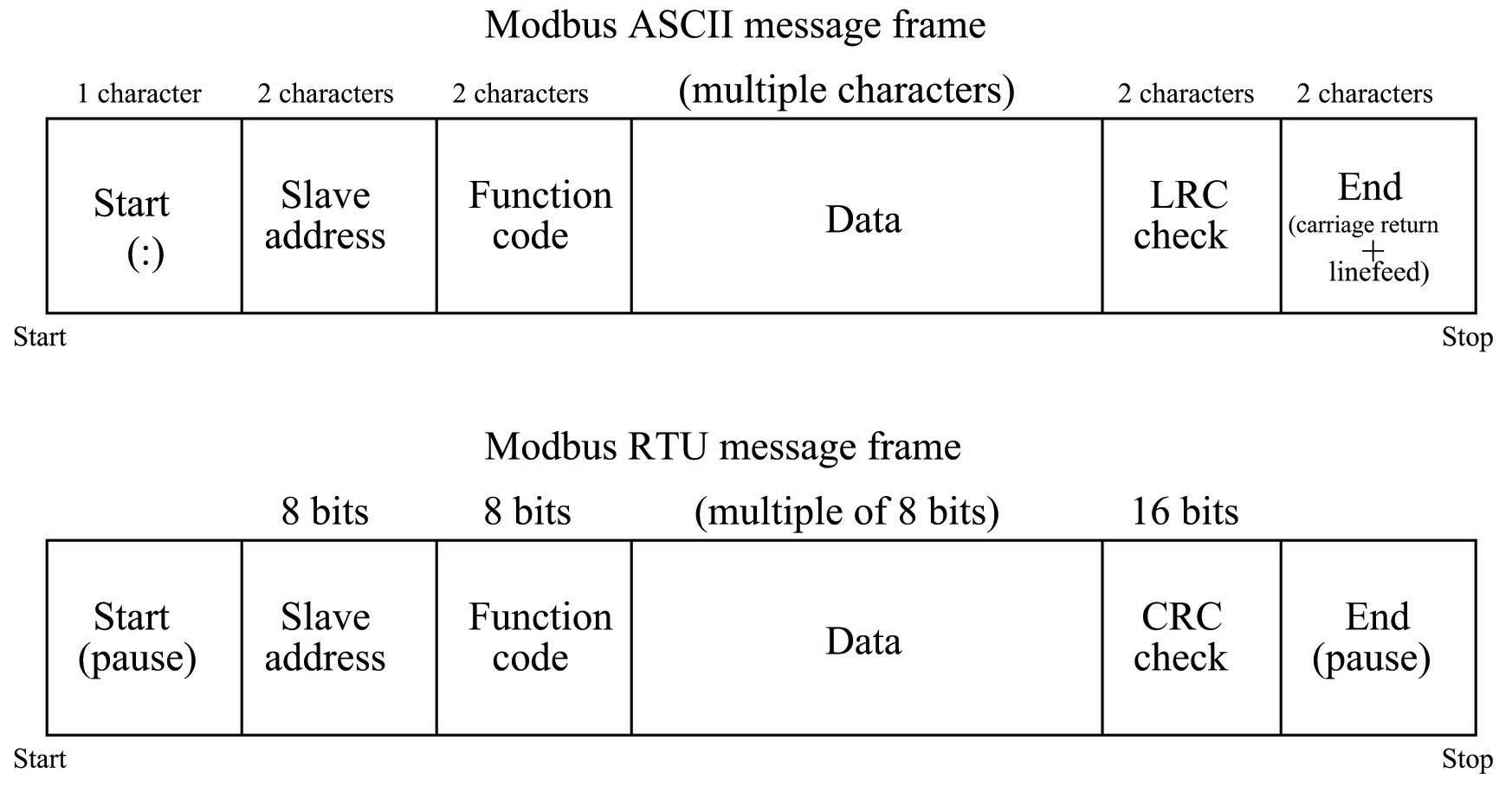
As you can see from a comparison of the two frames, ASCII frames require nearly twice446 the number of bits as RTU frames, making Modbus ASCII slower than Modbus RTU for any given data rate (bits per second).
The contents of the “Data” field vary greatly depending on which function is invoked, and whether or not the frame is issued by the master device or from a slave device. More details on Modbus “Data” field contents will appear in a later subsection.
Since Modbus is strictly a “layer 7” protocol, these message frames are usually embedded within other data frames specified by lower-level protocols. For example, the Modbus TCP standard encapsulates individual Modbus data frames as TCP/IP packets, which are then (usually) encapsulated again as Ethernet packets to arrive at the destination device. This “multi-layered” approach inherent to Modbus being such a high-level protocol may seem cumbersome, but it offers great flexibility in that Modbus frames may be communicated over nearly any kind of virtual and physical network type.
Modbus function codes and addresses
A listing of commonly-used Modbus function codes appears in the following table:
(decimal) & \cr
| Modbus code | Function | 01 | Read one or more PLC output ``coils'' (1 bit each) |
|---|---|---|---|
| 02 | Read one or more PLC input ``contacts'' (1 bit each) | ||
| 03 | Read one or more PLC ``holding'' registers (16 bits each) | ||
| 04 | Read one or more PLC analog input registers (16 bits each) | ||
| 05 | Write (force) a single PLC output ``coil'' (1 bit) | ||
| 06 | Write (preset) a single PLC ``holding'' register (16 bits) | ||
| 15 | Write (force) multiple PLC output ``coils'' (1 bit each) | ||
| 16 | Write (preset) multiple PLC ``holding'' registers (16 bits each) |
Live data inside of any digital device is always located at some address within that device’s random-access memory (RAM). The Modbus “984” addressing standard defines sets of fixed numerical addresses where various types of data may be found in a PLC or other control device. The absolute address ranges (according to the Modbus 984 scheme) are shown in this table, with each address holding 16 bits of data:
(decimal) & (decimal) & \cr
| Modbus codes | Address range | Purpose | 01, 05, 15 | 00001 to 09999 | Discrete outputs (``coils''), \textit{read/write} |
|---|---|---|---|---|---|
| 02 | 10001 to 19999 | Discrete inputs (``contacts''), \textit{read-only} | |||
| 04 | 30001 to 39999 | Analog input registers, \textit{read-only} | |||
| 03, 06, 16 | 40001 to 49999 | ``Holding'' registers, \textit{read/write} |
Note how all the Modbus address ranges begin at the number one, not zero as is customary for so many digital systems. For example, a PLC with sixteen analog input channels numbered 0 through 15 by the manufacturer may “map” those input registers to Modbus addresses 30001 through 30016, respectively.
While this fixed addressing scheme was correct for the original PLCs developed by Modicon, it almost never corresponds directly to the addresses within a modern Modbus master or slave device. Manufacturer’s documentation for Modbus-compatible devices normally provide Modbus “mapping” references so technicians and engineers alike may determine which Modbus addresses refer to specific bit or word registers in the device. In some cases the configuration software for a Modbus-compatible device provides a utility where you may assign specific device variables to standard Modbus register numbers. An example of a Modbus variable mapping page appears in this screenshot taken from the configuration utility for an Emerson Smart Wireless gateway, used to “map” data from variables within WirelessHART radio-based field instruments to Modbus registers within the gateway device where other devices on a wired network may read that data:
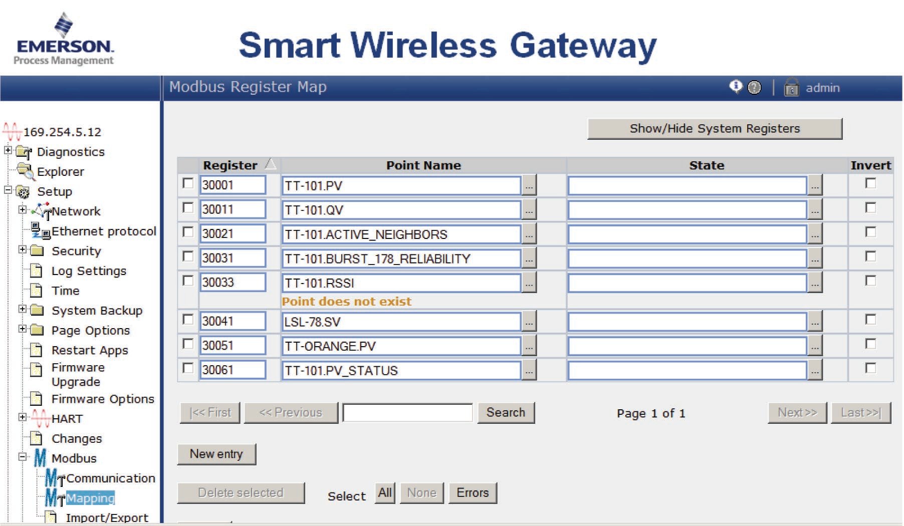
As you can see here, the primary variable within temperature transmitter TT-101 (TT-101.PV) has been mapped to Modbus register 30001, where any Modbus master device on the wired network will be able to read it. Likewise, the secondary variable within level switch LSL-78 (LSL-78.SV) has been mapped to Modbus register 30041.
It is important to note that Modbus registers are 16 bits each, which may or may not exactly fit the bit width of the device variable in question. If the device variable happens to be a 32-bit floating point number, then two contiguous Modbus registers must be used to hold that variable, only the first of which will likely appear on the Modbus mapping page (i.e. the Modbus map will only show the first Modbus register of that pair). If the device variable happens to be a boolean (single bit), then it is likely only one bit within the 16-bit Modbus register will be used, the other 15 bits being “wasted” (unavailable) for other purposes. Details such as this may be documented in the manual for the device performing the Modbus mapping (in this case the Emerson Smart Wireless Gateway), or you may be forced to discover them by experimentation.
Modbus relative addressing
An interesting idiosyncrasy of Modbus communication is that the address values specified within Modbus data frames are relative rather than absolute. Since each Modbus read or write function only operates on a limited range of register addresses, there is no need to specify the entire address in the data frame. For example, Modbus function code 02 reads discrete input registers in the device with an absolute address range of 10001 to 19999 (i.e. all the addresses beginning with the digit “1”). Therefore, it is not necessary for the “read” command function 02 to specify the first digit of the register address. Instead, the read command only needs to specify a four-digit “relative address” specifying how far up from the beginning of the address range (in this case, from 10001) to go.
An analogy to aid your understanding of relative addressing is to envision a hotel building with multiple floors. The first digit of every room number is the same as the floor number, so that the first floor only contains rooms numbered in the 100’s, the second floor only contains rooms numbered in the 200’s, etc. With this very orderly system of room numbers, it becomes possible to specify a room’s location in more than one way. For example, you could give instructions to go to room 314 (an absolute room number), or alternatively you could specify that same room as “number 14 (a relative room number) on the third floor”. To a hotel employee who only works on the third floor, the shortened room number might be easier to remember.
In Modbus, relative addresses are just a little bit more complicated than this. Relative addresses actually span a range beginning at zero, while absolute addresses begin with “1” as the least-significant digit. This means there is an additional offset of 1 between a Modbus relative address and its corresponding absolute address. Returning to the hotel analogy, imagine the very first room on the third floor was room 301 (i.e. there was no room 300) and that the relative address represented the number of rooms past that first room. In this unintuitive scheme, room 314 could be specified as “the 13th room after the starting room on the third floor”. If this seems needlessly confusing, you are not alone. Welcome to Hotel Modbus.
A few examples are given here for illustration:
- Read the content of contact register 12440: Modbus read function 02; relative address 2439
- Read the content of analog input register 30050: Modbus read function 04; relative address 49
- Read the content of holding register 41000: Modbus read function 03; relative address 999
- Write multiple output coils in register 00008: Modbus write function 15; relative address 7
In each case, the pattern is the same: the relative address gets added to the first address of that range in order to arrive at the absolute address within the Modbus device. Referencing the first example shown above: 2439 (relative address) + 10001 (first address of register range) = 12440 (absolute address).
Thankfully, the only time you are likely to contend with relative addressing is if you program a computer using some low-level language such as assembly or C++. Most high-level industrial programming languages such as Function Block or Ladder Diagram make it easy for the end-user by allowing absolute addresses to be directly specified in the read and write commands. In a typical PLC program, for example, you would read contact register 12440 by simply specifying the number 12440 within the address field of a “read 02” instruction.
The following listing shows code (written in the C language) utilizing the open-source libmodbus function library instructing a computer to access 16-bit integer data from four Modbus “holding” registers (absolute addresses 49001 through 49004) via Modbus/TCP. The device’s IP address is 192.169.0.10 and port 502 is used for the TCP connection:
C code listing
#include #include modbus_t *Device; int main (void) { int read_count; uint16_t inreg_word[4]; Device = modbus_new_tcp ("192.168.0.10", 502); modbus_set_error_recovery (Device, MODBUS_ERROR_RECOVERY_LINK); read_count = modbus_read_registers (Device, 9000, 4, inreg_word); printf("Number of registers read = %i \n", read_count); printf("Value of register 49001 = %i \n", inreg_word[0]); printf("Value of register 49002 = %i \n", inreg_word[1]); printf("Value of register 49003 = %i \n", inreg_word[2]); printf("Value of register 49004 = %i \n", inreg_word[3]); modbus_close (Device); modbus_free (Device); return read_count; }Note how the starting address passed to the read function is specified in relative form (9000), when in fact the desired absolute starting address inside the device is 49001. The result of running this code is shown here, the Modbus device in question being an Emerson Smart Wireless Gateway at 4:00 PM (i.e. 16:00 military time) on March 22, 2016. These four registers (49001 through 49004) happen to contain date and time information (year, month, day, and hour) stored in the device:
Number of registers read = 4
Value of register 49001 = 2016
Value of register 49002 = 3
Value of register 49003 = 22
Value of register 49004 = 16This next listing shows similar code (also written in the C language447) accessing 16-bit integer data from three Modbus “analog input” registers (absolute addresses 30015 through 30017) via Modbus/TCP from the same device as before:
C code listing
#include #include modbus_t *Device; int main (void) { int read_count; uint16_t inreg_word[3]; Device = modbus_new_tcp ("192.168.0.10", 502); modbus_set_error_recovery (Device, MODBUS_ERROR_RECOVERY_LINK); read_count = modbus_read_input_registers (Device, 14, 3, inreg_word); printf("Number of registers read = %i \n", read_count); printf("Value of register 30015 = %i \n", inreg_word[0]); printf("Value of register 30016 = %i \n", inreg_word[1]); printf("Value of register 30017 = %i \n", inreg_word[2]); modbus_close (Device); modbus_free (Device); return read_count; }Note once again how the relative starting address specified in the code (14) maps to the absolute Modbus register address 30015, since analog input registers begin with the address 30001 and relative addresses begin at 0.
When using the
libmodbusC/C++ library, the distinction between reading “analog input” registers (address range 30001 to 39999) and “holding” registers (address range 40001 to 49999) is made by the particularlibmodbusfunction called. To read “analog input” registers in the 3XXXX address range, you use themodbus_read_input_registers()function. To read “holding” registers in the 4XXXX address range, you use themodbus_read_registers()function. This subtle difference in function names is important. Refer back to the two previous code examples to verify for yourself which function call is used in each of the register-reading applications.Modbus function command formats
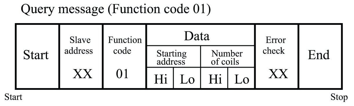
Every Modbus data frame, whether ASCII or RTU mode, has a field designated for “data.” For each Modbus function, the content of this “data” field follows a specific format. It is the purpose of this subsection to document the data formats required for common Modbus functions, both the “Query” message transmitted by the Modbus master device to a slave device, and the corresponding “Response” message transmitted back to the master device by the queried slave device.
Since each Modbus data frame is packaged in multiples of 8 bits (RTU), they are usually represented in text as individual bytes (two hexadecimal characters). For example, a 16-bit “word” of Modbus data such as
1100100101011011would typically be documented asC9 5Bwith a deliberate space separating the “high” (C9) and “low” (5B) bytes.Function code 01 – Read Coil(s)
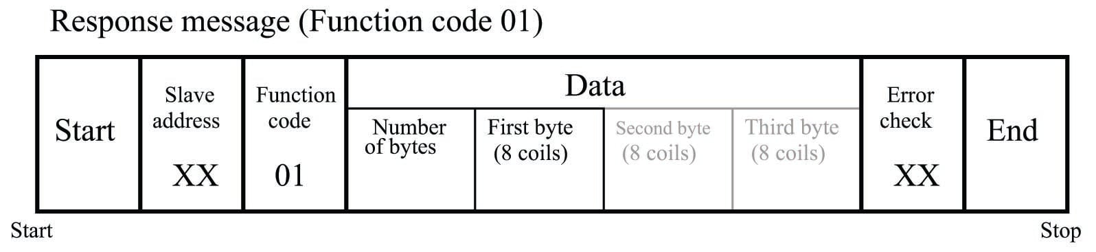
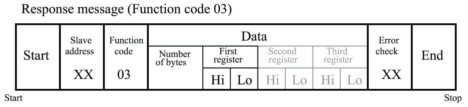
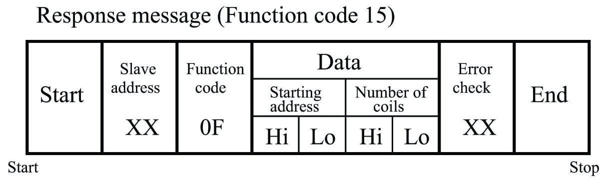
This Modbus function reads the statuses of slave device discrete outputs (“coils”) within the slave device, returning those statuses in blocks of eight (even if the “number of coils” specified in the query is not a multiple of eight!). Relevant Modbus addresses for this function range from 00001 to 09999 (decimal) but the starting address is a hexadecimal number representing the \((n-1)^{th}\) register from the beginning of this range (e.g. decimal address 00100 would be specified as hexadecimal
00 63).
Note that the second and third bytes representing coil status are shown in grey, because their existence assumes more than one byte worth of coils has been requested in the query.
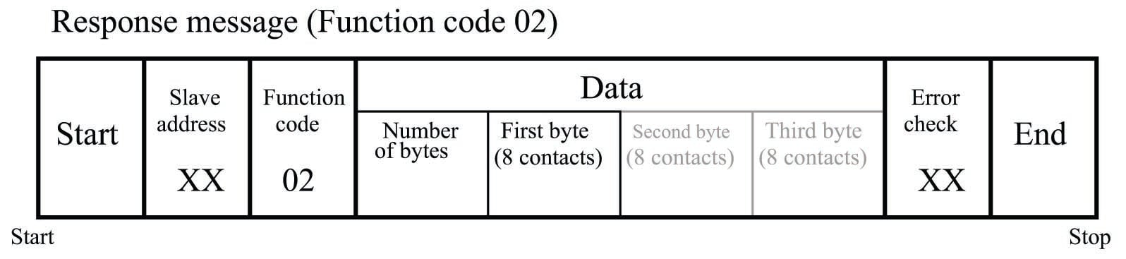
Function code 02 – Read Contact(s)
This Modbus function reads the statuses of slave device discrete inputs (“contacts”) within the slave device, returning those statuses in blocks of eight (even if the “number of contacts” specified in the query is not a multiple of eight!). Relevant Modbus addresses for this function range from 10001 to 19999 (decimal), but the starting address is a hexadecimal number representing the \((n-1)^{th}\) register from the beginning of this range (e.g. decimal address 10256 would be specified as hexadecimal
00 FF).
Function code 03 – Read Holding Register(s)
This Modbus function reads the statuses of “holding” registers within the slave device, with the size of each register assumed to be two bytes (16 bits). Relevant Modbus addresses for this function range from 40001 to 49999 (decimal), but the starting address is a hexadecimal number representing the \((n-1)^{th}\) register from the beginning of this range (e.g. decimal address 40980 would be specified as hexadecimal
03 D3).
Note that since the query message specifies the number of registers (each register being two bytes in size), and the response message replies with the number of bytes, the response message’s “number of bytes” field will have a value twice that of the query message’s “number of registers” field. Note also that the maximum number of registers which may be requested in the query message (65536) with “high” and “low” byte values grossly exceeds the number of bytes the response message can report (255) with its single byte value.
Function code 04 – Read Analog Input Register(s)
This Modbus function is virtually identical to 03 (Read Holding Registers) except that it reads “input” registers instead: addresses 30001 through 39999 (decimal). As with all the Modbus relative addresses, the starting address specified in both messages is a hexadecimal number representing the \((n-1)^{th}\) register from the beginning of this range (e.g. decimal address 32893 would be specified as hexadecimal
0B 4C).
Note that since the query message specifies the number of registers (each register being two bytes in size), and the response message replies with the number of bytes, the response message’s “number of bytes” field will have a value twice that of the query message’s “number of registers” field. Note also that the maximum number of registers which may be requested in the query message (65536) with “high” and “low” byte values grossly exceeds the number of bytes the response message can report (255) with its single byte value.
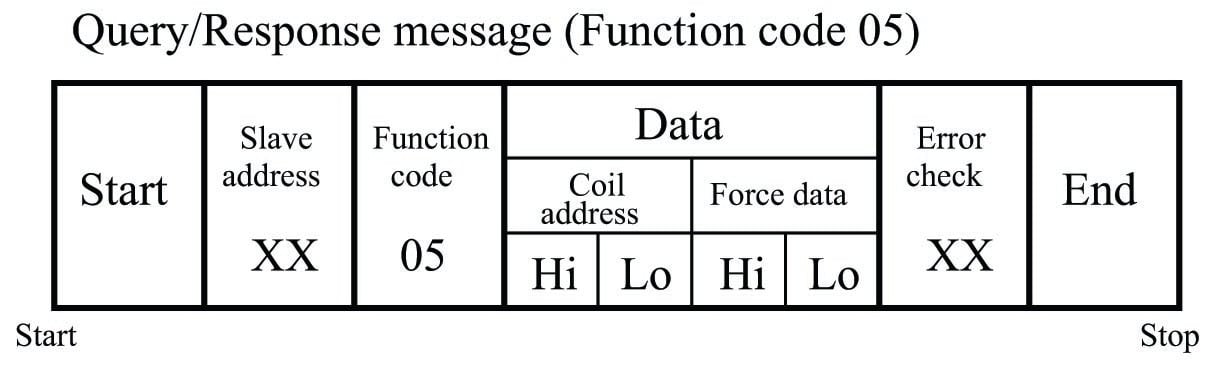
Function code 05 – Write (Force) Single Coil
This Modbus function writes a single bit of data to a discrete output (“coil”) within the slave device. Relevant Modbus addresses for this function range from 00001 to 09999 (decimal) but the starting address is a hexadecimal number representing the \((n-1)^{th}\) register from the beginning of this range (e.g. decimal address 07200 would be specified as hexadecimal
1C 1F).
The “force data” for a single coil consists of either
00 00(force coil off) orFF 00(force coil on). No other data values will suffice – anything other than00 00orFF 00will be ignored by the slave device.A normal response message will be a simple echo (verbatim repeat) of the query message.
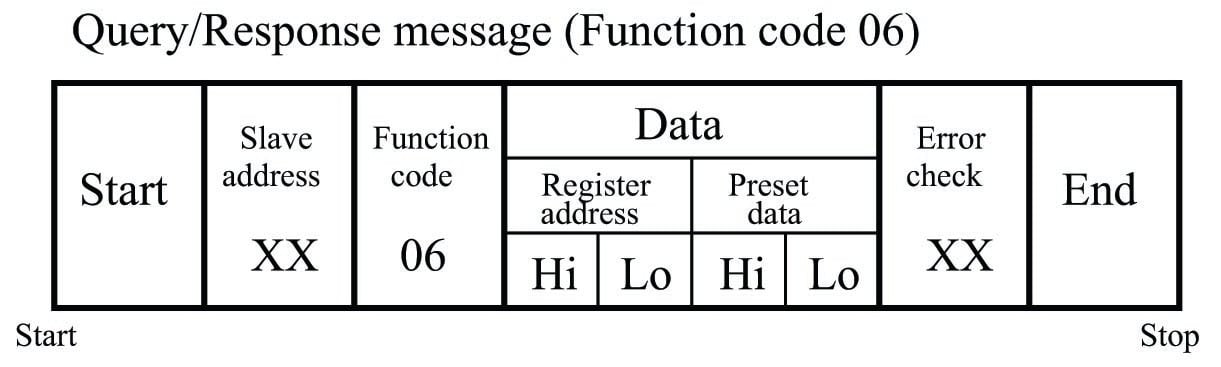
Function code 06 – Write (Preset) Single Holding Register
This Modbus function writes data to a single “holding” register within the slave device. Relevant Modbus addresses for this function range from 40001 to 49999 (decimal) but the starting address is a hexadecimal number representing the \((n-1)^{th}\) register from the beginning of this range (e.g. decimal address 40034 would be specified as hexadecimal
00 21).
A normal response message will be a simple echo (verbatim repeat) of the query message.
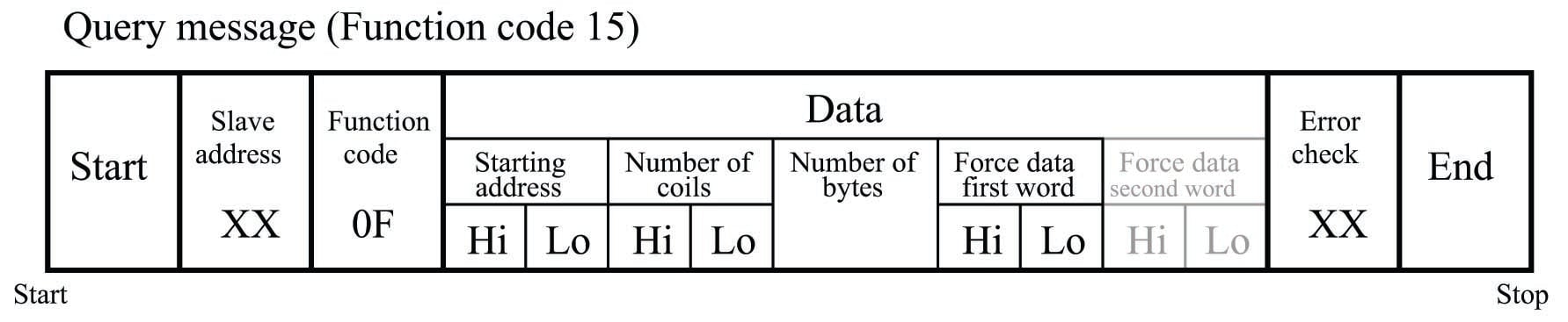
Function code 15 – Write (Force) Multiple Coils
This Modbus function writes multiple bits of data to a set of discrete outputs (“coils”) within the slave device. Relevant Modbus addresses for this function range from 00001 to 09999 (decimal) but the starting address is a hexadecimal number representing the \((n-1)^{th}\) register from the beginning of this range (e.g. decimal address 03207 would be specified as hexadecimal
0C 86).
Note that the query message specifies both the number of coils (bits) and the number of bytes.
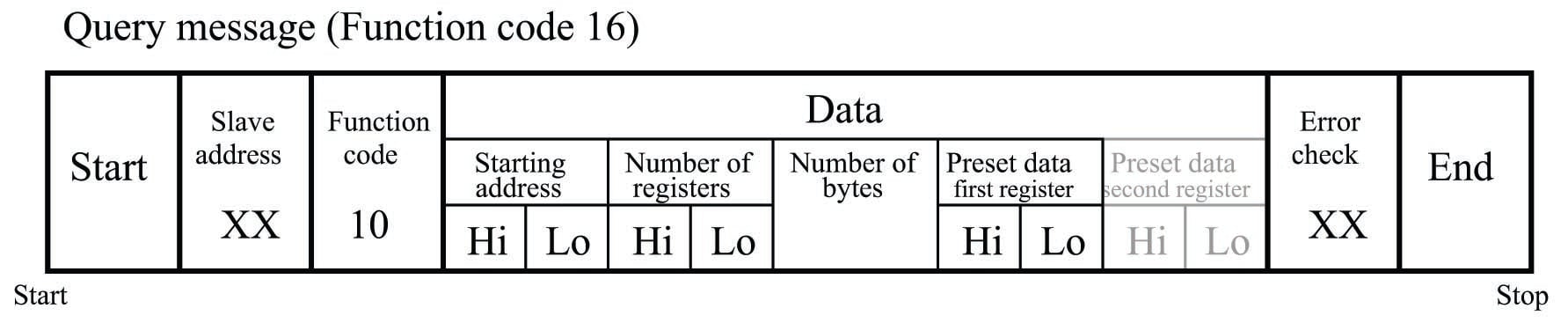
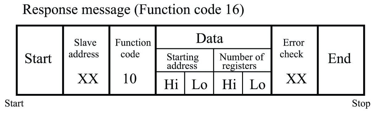
Function code 16 – Write (Preset) Multiple Holding Register
This Modbus function writes multiple words of data to a set of “holding” registers within the slave device. Relevant Modbus addresses for this function range from 40001 to 49999 (decimal) but the starting address is a hexadecimal number representing the \((n-1)^{th}\) register from the beginning of this range (e.g. decimal address 47441 would be specified as hexadecimal
1D 10).
Note that the query message specifies both the number of registers (16-bit words) and the number of bytes, which is redundant (the number of bytes must always be twice the number of registers, given that each register is two bytes448 in size). Note also that the maximum number of registers which may be requested in the query message (65536) with “high” and “low” byte values grossly exceeds the number of bytes the response message can report (255) with its single byte value.
Floating-point values in Modbus
The ANSI/IEEE 754-1985 standard for floating-point data representation specifies 32 bits for the most basic (“single-precision”) form of floating-point number. Modbus input and holding registers, however, are specified by the Modbus standard to be 16 bits each. Therefore, if we wish to read or write a floating-point value within a Modbus slave device, we must issue a Modbus command to read or write two 16-bit registers representing the one 32-bit floating-point value. The task of piecing together two 16-bit numbers into a single 32-bit number, or splitting apart one 32-bit number into two 16-bit numbers, is left to the master device. If the master device in question is a modern PLC or HMI unit, this 16/32 bit conversion is most likely handled by the Modbus read/write instruction, so that all you must do is specify the first Modbus address for the pair of registers and the read/write instruction takes care of all other details. If, however, you are programming a computer using a low-level language, you must contend with these details in your own code.
A significant problem here is a lack of standardization among Modbus device manufacturers regarding exactly how 32-bit floating-point numbers are to be split up into two 16-bit register values. Some manufacturers simply take the 32 bits of the floating-point number and break them up into two sequential 16-bit numbers in order (denoted “ABCD” ordering, with each letter representing one byte of the original 32-bit floating-point number). Others reverse the order of the first and second 16-bit pieces (i.e. “CDAB” byte ordering). Others yet treat the 32-bit floating-point value as a set of four independent bytes which may be shuffled in any of several different orderings (e.g. “BADC”, “DCBA”, etc.). The Modbus standard offers no guidance on this matter, leaving the choice up to device manufacturers.
When programming in the C or C++ computer languages, a convenient strategy for splicing or splitting these different bit-length numbers is to make use of the union structure. A “union” in these languages is a reserved space in the computer’s memory which may be addressed by elements of different bit-length. For example, the following snippet of C code shows how to declare a union called
junkwhich is 32 bits in size, and which may be addressed as a single 32-bit floating-point value calledjunk.fp, or as two 16-bit integer values calledjunk.intg[0]andjunk.intg[1], or as four 8-bit values calledjunk.by[0]throughjunk.by[3]:C code listing
union { float fp; uint16_t intg[2]; uint8_t by[4]; } junk;This union could be written with 32 bits of data (in one step, as a floating-point value) and then read as either two 16-bit values and/or as four 8-bit values. The union structure gives any software developer the ability to reference a common area of computer memory as different number types.
The following code is a complete program reading two consecutive 16-bit “analog input” registers at addresses 30020 and 30021 and combining them into a single 32-bit floating-point value with “CDBA” ordering. Both the original 16-bit register values as well as the final floating-point value are displayed on the computer’s screen upon execution:
C code listing
#include #include modbus_t *Device; int main (void) { int read_count; union { uint16_t word[2]; uint8_t byte[4]; } in; union { float real; uint8_t byte[4]; } out; Device = modbus_new_tcp ("192.168.0.10", 502); modbus_set_error_recovery (Device, MODBUS_ERROR_RECOVERY_LINK); read_count = modbus_read_input_registers (Device, 19, 2, in.word); printf("Value of 16-bit register 30020 = %i \n", in.word[0]); printf("Value of 16-bit register 30021 = %i \n", in.word[1]); out.byte[0] = in.byte[2]; out.byte[1] = in.byte[3]; out.byte[2] = in.byte[0]; out.byte[3] = in.byte[1]; printf("Value of 32-bit floating-point number = %f \n", out.real); modbus_close (Device); modbus_free (Device); return read_count; }This program utilizes a pair of 32-bit unions (one called
inand the other calledout) to do the byte-swapping. First, the two 16-bit registers read by themodbus_read_input_registers()function are stored in theinstructure as two 16-bit “words” addressedin.word[0]andin.word[1]. Then, those two words’ worth of data are addressed as four bytes, each one written to a different place within theoutunion by the four assignment statements. Note howout.byte[0]is assigned the value stored withinin.byte[2]and so on: this is how the CDBA ordering is specified. One could specify ABCD ordering or DCBA ordering or any other combination of those four bytes by assigning the fouroutbytes to values of differentinbytes, and the code would be just as straightforward to understand.If you are fortunate enough, the Modbus library you are using will come complete with functions designed to take pairs of 16-bit registers and convert them into single floating-point numbers. At the time of this writing (2016), the free libmodbus library offers such functions. One of those functions (
modbus_get_float()) is shown here for illustrative purposes, reading the contents of analog input registers 32999 and 33000 and displaying the converted (“ABCD”-ordered) floating-point value:C code listing
#include #include modbus_t *Device; int main (void) { int read_count; uint16_t word[2]; float real; Device = modbus_new_tcp ("192.68.0.10", 502); modbus_set_error_recovery (Device, MODBUS_ERROR_RECOVERY_LINK); read_count = modbus_read_input_registers (Device, 2998, 2, word); printf("Value of 16-bit register 32999 = %i \n", word[0]); printf("Value of 16-bit register 33000 = %i \n", word[1]); real = modbus_get_float(word); printf("Value of 32-bit floating-point number = %f \n", real); modbus_close (Device); modbus_free (Device); return read_count; }Sadly, you will often find that the arbitrary byte ordering used by any particular Modbus slave device manufacturer is poorly documented, if at all. This means you may have to experiment with different byte orderings before achieving success reading or writing floating-point data. Some Modbus device manufacturers are thoughtful enough to actually provide configurable options for how their 32-bit floating-point values will be represented within the slave device. Likewise, many Modbus master device manufacturers (e.g. PLCs and HMIs) provide options for how to read and write floating-point values in their Modbus read and write instructions, because they do not know whose Modbus slave device you may be communicating with.


thank you