Facebook
 Google
 GitHub
 Linkedin
What is Internet Protocol (IP)?
I remember first learning about the world-wide Internet, and wondering what it actually looked like. The first vision entering my mind when people told me about a computer network spanning nearly all of the United States and many other parts of the world was that of a thick cable strung along telephone poles and buried underground, with a big sign on it saying “Internet.” I also remember well the shock of learning that although the Internet made use of several high-capacity networks (called backbones) connecting large data centers in different cities, the real “magic” of the Internet did not reside in any particular cable or link. Instead, what made the Internet so widespread and accessible was actually a protocol allowing for the free exchange of data along and between disparate systems. This “protocol” allowed digital data to be packaged in such a way that it could be sent along nearly any kind of communications link (from copper wires to fiber-optic to radio waves) – and indeed along multiple pathways between the same two points – while arriving at the destination intact. Thus, the Internet was akin to a random patchwork of existing communications pathways pressed into coordinated service by the sharing of a common “language.” In this section, we will investigate the protocol at the heart of the Internet, appropriately called Internet Protocol, or IP.
Physical network standards such as Ethernet only define aspects relevant to lower layers of the OSI Reference Model. While these details are essential for communication to occur, they are not enough on their own to support a wide-spread communications system. For this reason, network standards such as EIA/TIA-485 and Ethernet almost always comprise the lower layer(s) of a more complex communications protocol capable of managing higher-order addresses, message integrity, “sessions” between computers, and a host of other details.
Internet Protocol (IP) manages network addresses and data handling over a much larger physical domain than Ethernet is able to. The basic principle of IP is that large digital messages may be broken down into smaller pieces, then each piece buffered with additional data bits to form packets specifying (among other things) how the pieces are to be directed to their proper destination(s). The completed packets are then transmitted individually and received individually, where they may be reassembled at the receiver to form the original message in its entirety. An analogy for this process is an author with a printed paper manuscript for a book, who needs to get her manuscript to a print shop across town. Unfortunately, the mail service in this town cannot transport the bulky manuscript in one piece, so the author divides the manuscript into 10-page bundles and mails each of these bundles in its own package to the print shop. The individual packages may not make it to the print shop on the same day, or even in the correct order, but the addressing on each package directs the postal service to deliver each of them to the proper location.
This strategy for transmitting large digital messages is at the heart of the Internet: data sent from one computer to another over the Internet is first broken down into packets, which are then routed over a variety of pathways to their destination. The packets need not take the same route to their destination, nor do they even need to travel along the same kinds of networks. The receiving computer must then reassemble those packets in the proper order to re-create the original data. This “packetization” of data allows multiple messages to be interleaved on a network (i.e. the network’s bandwidth being alternately used to convey pieces of completely different messages, rather than being reserved for one whole message at a time) as well as permitting alternate routes that the message may take in order to traverse large physical distances. In a web-shaped network where multiple pathways exist between any two points, the ability to direct packets of data along alternate routes increases the reliability of that network: failure of any one routing node or communications pathway does not necessarily prevent data from reaching its final destination. This fault tolerance was one of the design criteria for what came to be the Internet when it was first developed by the United States’ Department of Defense.
Interestingly, the task of portioning a large block of digital data into packet-sized pieces, and then re-assembling those pieces together in the proper order to form the original data block, is not the task of IP, but rather the task of some higher-level protocol such as TCP (Transmission Control Protocol). Internet Protocol (IP) merely specifies how the individual packets are to be marked and routed to their proper destination(s). To use the manuscript analogy again, IP is the postal service with its system of mailing addresses, postage stamps, and labeling conventions, while TCP (or some other higher-level protocol) is the author and publisher who divide the manuscript into smaller bundles and then reassemble those bundles into the original manuscript, respectively. For this reason, IP is not a complete solution for large-scale network communication on its own. This is why the Internet’s central protocol is referred to as TCP/IP, the two protocols working together to ensure coordinated and reliable communication of packetized data over wide areas.
IP addresses
IP is a “layer 3” technology, being concerned with network-wide addresses for routing information between two different locations. IP is not concerned with the details of communication along any particular wire or fiber-optic cable. It is not “aware” of how bits are represented electrically, or what kind of connectors are used to couple cables together. IP is only concerned with “networks” in the broad sense of the word, as abstract collections of computers that are somehow (it doesn’t care exactly how) connected to each other.
Networking equipment (DCE) designed to pay attention to IP addresses for routing purposes are called, not surprisingly, routers. Their purpose is to direct packets to their appropriate destinations in the shortest amount of time.
In order for the Internet Protocol to specify where packets are coming from and where they are going to, each source and destination must be marked with its own IP address. IP version 4 (IPv4) uses 32-bit addresses, usually expressed as four octets (four bytes) written using decimal numbers. For example:
IP address 00000000 00000000 00000000 00000000 is written as 0.0.0.0
IP address 11111111 11111111 11111111 11111111 is written as 255.255.255.255
IP address 10101001 11111010 00101101 00000011 is written as 169.250.45.3
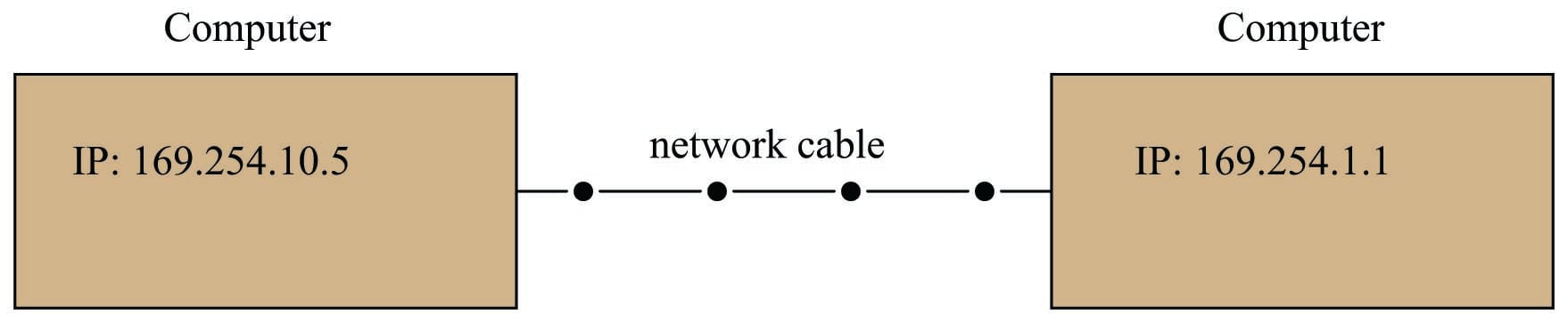
In order for two inter-connected computers to exchange data using Internet Protocol, each one must have a unique IP address:
At first, this may seem redundant. Doesn’t each and every Ethernet device already have its own unique “MAC address” 48 bits in length to distinguish it from every other Ethernet device in existence? If so, why add another set of identifying addresses to the system?
This is true – Ethernet devices are already uniquely addressed – but those MAC addresses serve different purposes than IP addresses. Recall that Ethernet is a standard only at layers 1 and 2, and is not “aware” of any higher-level concerns. Ethernet MAC addresses are useful to switching hubs and other Ethernet DCE devices tasked with management of Ethernet data frames, but those MAC addresses – unique as they may be – have little relevance in the greater picture of IP where we must fragment and reassemble messages over very large-scale networks. More importantly, the reason we need IP addresses is to be able to use interconnecting networks other than Ethernet. For example, two computers may be connected to each other with a simple EIA/TIA-232 cable (or even using radio transceiver units for a “wireless” connection) instead of Ethernet, but still use Internet Protocol to route packets to their destinations. By having its own dedicated addressing scheme, IP ensures computers can send and receive data packets with no regard to physical interconnection details, channel arbitration methods, or anything else in between. In a sense, IP is the “glue” that holds disparate networks together, and makes something like a world-wide Internet possible when so many different network types exist to connect digital devices together. If we attempted to use Ethernet MAC addresses for the same purpose, the entire Internet would have to consist solely of Ethernet networks!
A helpful analogy is to think of Ethernet MAC addresses like Social Security numbers for United States citizens, while IP addresses are like street addresses used to route mail. Each US citizen should have their own unique Social Security number, shared by no one else. This number is used for many purposes, including identification on Federal tax documents, to help route specific information (such as income records and Social Security payments) to the proper people. Despite the uniqueness of these numbers, though, people still need separate mailing addresses in order to receive mail through the postal service and other package distribution agencies. The mailing address serves a different purpose than the Social Security “address” each US citizen possesses. Furthermore, the existence of separate mailing addresses ensures even non-citizens living in the United States (e.g. foreign students, ambassadors, etc.) who have no Social Security numbers still have a way to send and receive mail. The mapping of device MAC addresses to IP addresses is handled by a protocol called ARP (Address Resolution Protocol) discussed later in this chapter.
The “ping” utility
Computers enabled to communicate using Internet Protocol (IP) are equipped with a utility program named ping useful for detecting the presence of other IP-enabled computers connected to the same network. The classic format of this program is execution by typing the word “ping” at the computer’s command-line interface followed by the IP address of the other computer you wish to detect the presence of. For example, if I wished to check for the presence of a computer on the network with an IP address of 133.82.201.5, I would type this command at my computer’s command line and press the “Enter” key:
ping 133.82.201.5
The ping utility works by sending a very short digital message to the specified IP address, requesting a reply from that computer (usually with multiple attempts). The ping command as implemented on the Microsoft Windows (XP) operating system typically makes four attempts before quitting. Some other operating systems’ implementation of ping continue indefinitely until halted by the user with the “Control-C” keystroke interrupt combination.
When diagnosing problems with IP-enabled network devices, few utilities are as immediately useful as ping. Networking professionals commonly use the word “ping” as a verb, as in “I tried to ping that computer, but it gave no response.” There are many reasons why a computer might fail to respond to a ping query, but a successful ping attempt proves several things:
- The destination device is powered up and its IP functionality is working
- All network devices (DCE) between your computer and the destination device are communicating
- All cables necessary for the communication of data between your computer and the destination are functional
- Both your computer and the destination device are on the same subnet (this topic covered in more detail later)
Since ping requires the first three layers of the OSI model to properly function (Physical, Data Link, and Network layers), using this as a diagnostic test neatly identifies where in the OSI model a problem exists. If two computers are not communicating with each other as they should but the ping utility works between them, the communication fault must lie within one of the upper OSI layers (e.g. Transport, Session, Presentation, or Application). Thus, we see the ping utility as a tool for “divide-and-conquer” style troubleshooting, where we may prove good connections between certain devices and thereby narrow the scope of the problem by elimination.
IPv4 address ranges
Given the addressing purpose of Internet Protocol (to designate addresses over an extremely large collection of digital communication devices), addresses must be chosen with care. IP version 4 uses a 32-bit field to designate addresses, limiting its address capacity to \(2^{32}\) unique addresses. As large as this number is, it is not enough to uniquely identify all Internet-capable devices worldwide. The inventors of IP did not dream their Internet would grow to the proportions it has today. Let this be a lesson to all those involved with computers: the future is usually bigger than you think! A variety of clever techniques has been developed to deal with this shortage of IP addresses. One of them is to dynamically assign addresses to Internet-connected computers only when they are turned on. This is how most personal Internet connections work: when you power up your personal computer to connect to the Internet, your service provider assigns you a temporary IP address through a protocol called DHCP (Dynamic Host Configuration Protocol). Your provider then forces you to relinquish this temporary IP address when you shut down your computer, so someone else may use it for theirs.
The Internet Corporation for Assigned Names and Numbers, or ICANN, is the organization responsible for assigning IP addresses to Internet users worldwide (among other tasks). This group has designated certain IP address ranges specific to internal (i.e. Local Area Network, or LAN) network devices, which shall never be used “publicly” to address devices on the world-wide Internet. These specially-designated “private” LAN address ranges are as follows:
10.0.0.0 to 10.255.255.255
172.16.0.0 to 172.31.255.255
192.168.0.0 to 192.168.255.255
Additionally, all computers have their own special loopback IP address, used to send IP message packets to itself for certain purposes (including diagnostics): 127.0.0.1. This IP address is completely virtual, not associated with any network hardware at all. Therefore, the ping command executed on any computer should always be able to detect address 127.0.0.1, regardless of the status or even existence of actual network hardware (cards or interfaces) on that computer. Failure of the ping command to detect the loopback address is a sign that the computer’s operating system is not configured to use Internet Protocol.
A computer’s loopback address may have uses other than diagnostic. Some computer applications are network-oriented by nature, and rely on IP addresses even if the application is performing some local function rather than a function between computers on an actual network. The X-windows graphic-user interface (GUI) system popularly used on UNIX operating systems is an example of this, referencing the loopback address to form a connection between client and server applications running on the same computer.
Subnetworks and subnet masks
IP (version 4) addresses are used in conjunction with something called subnet masks to divide IP networks into “subnetworks.” A “subnetwork” is a range of IP-addressed devices allowed to communicate with each other. You may think of the subnet mask to be a sort of “filter” used to identify IP addresses belonging to the proper range.
The subnet mask works as a bitwise filter, identifying those bits in the IP address defining the subnetwork. For example, if the subnet mask on a computer is set to 255.0.0.0 (binary 11111111 00000000 00000000 00000000), it means the first 8 bits of the IP address define the subnetwork, and thus the computer is only allowed to communicate with another computer belonging to the same subnetwork (i.e. having the same first octet in its IP address).
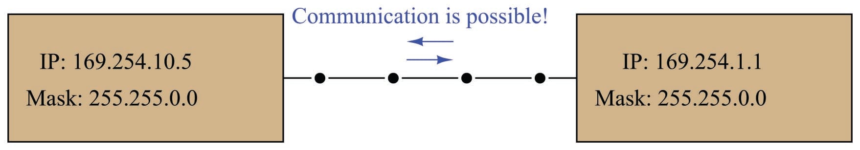
A set of examples showing two interconnected computers with differing IP addresses (and in some cases, different masks) illustrates how this works. In the first example, two computers with IP addresses differing in the last two octets are able to communicate because their subnets are the same (169.254):
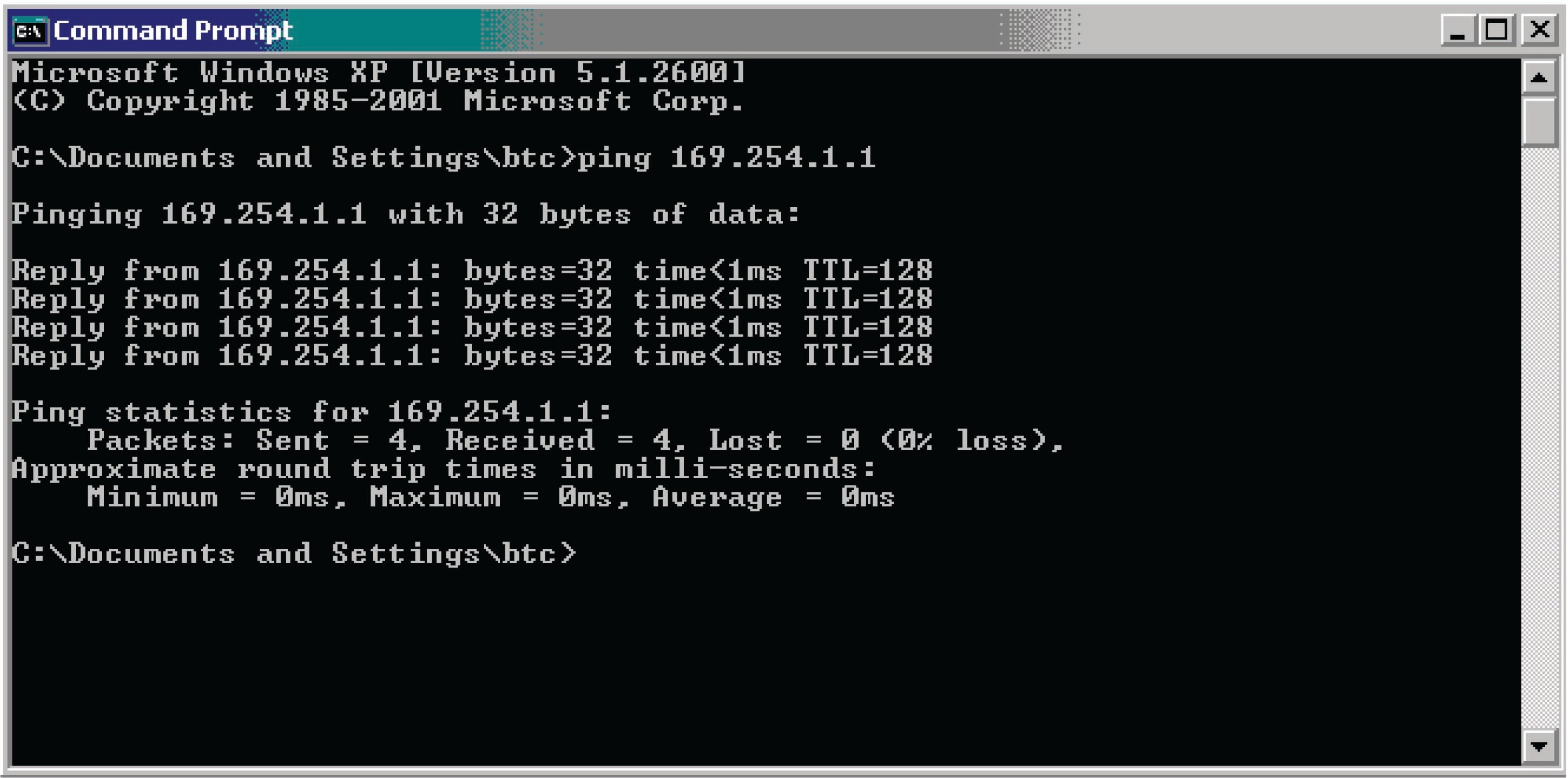
We may check to see the IP addresses and subnet masks are correct by using the ping command. A screenshot of ping being used on a personal computer running the Microsoft Windows XP operating system is shown here:
In the next example, we see two computers with the same mask value, but with different address values in the octets designated by their masks. In other words, these two computers belong to different subnets: one to 167.254 and the other to 169.254, and as a result they are not allowed to communicate with each other using Internet Protocol. The resulting error messages generated by the ping utility are shown in this diagram:

In the last example, we see two computers having different mask values as well as different IP addresses. The subnet of the left-hand computer is 169.254.10 while the subnet of the right-hand computer is 169.254:
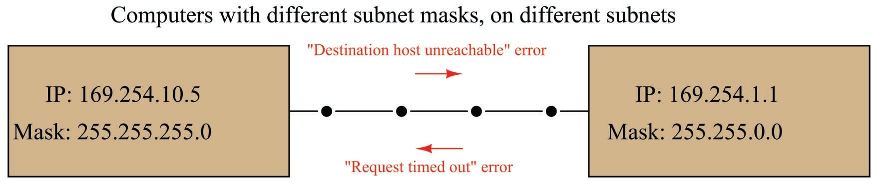
The computer on the left may only communicate with IP addresses matching in the first three octets (169.254.10). Seeing that the destination address for the second computer does not match in its third octet, ping returns a “Destination host unreachable” error message when executed from the left-hand computer.
When the computer on the right attempts to communicate with (“ping”) the computer on the left, it is allowed to transmit to that computer because its mask only screens for agreement in the first two octets (169.254), which happen to match. However, the computer on the left is not allowed to transmit to the computer on the right because of its more restrictive subnet, and so ping running on the right-hand computer returns a “Request timed out” error message because it never receives a reply from the left-hand computer to any of its queries.
With just two computers connected by a single cable, the concept of subnetworks and masks seems useless, and indeed it is on this small of a scale. However, “subnetting” is a useful technique for managing high traffic loads on large networked systems using IP addresses, and so it is commonly seen in many local area networks (LANs) such as those found at industry and commercial sites.
While many IPv4-compliant computers designate both the IP address and the subnet mask values as sets of “dotted-decimal” numbers with each decimal (0-255) representing an “octet” of eight bits in the 32-bit IPv4 address space (e.g. IP = 169.254.5.1 and Mask = 255.255.0.0), a more modern designation for subnets is to append the device’s IP address with a forward slash character and a decimal number specifying how many bits are used to specify the subnet.
To illustrate by example, consider a computer having the IP address 169.254.5.1 and a mask value of 255.255.0.0 (thus specifying that it belongs to the subnetwork 169.254), we could alternatively state that computer’s IP address as 169.254.5.1/16. The “16” means that the first sixteen bits of its IP address define its subnet. To cite another example, a computer with an IP address of 192.168.35.100 and a subnet mask of 255.255.255.0 could have its address alternatively written as 192.168.35.100/24. The “24” tells us the first 24 bits (first three octets) of the IP address define its subnetwork: this computer belongs to the subnetwork 192.168.35.
The ping diagnostic utility program may be used to search for unknown IP addresses on a known subnet. This may be done by “pinging” to the broadcast address for that subnet: an IP address formed by the known subnet numbers, followed by all binary 1’s filling the unknown bit spaces. For example, you could use ping to search for devices on the subnet 156.71 (subnet mask 255.255.0.0) by using the following command:
ping 156.71.255.255
Routing tables
Devices on an IP-compliant network need to know how to best route IP data packets from one location to another. In the case of special router devices managing traffic on the Internet, optimum packet routes are determined by a number of different criteria (e.g. degree of congestion in a route, the fewest number of “hops” from one router to another, geographical distance, etc.), updated continually by sophisticated algorithms operating within the routers. Data for these optimum routes are stored in lists called routing tables.
Personal computers also have routing tables, which may be modified by the user. An application where you may need to modify the routing table of a personal computer is the case of enabling that computer to communicate with a brand-new device installed on the industrial network, whose subnetwork ID differs from the other devices on that network. Many network-ready industrial instruments are shipped from the manufacturer with default subnets of 192.168.1. It is quite possible that the subnet of the industrial network you intend to have the device operate on is different from this default factory-configuration. This in itself is not necessarily a problem, as IP addresses and subnet mask values of IP-enabled devices are always user-configurable. However, if the only method of configuring this new device is by communicating to it through an IP network connection, you are faced with a Catch-22: how do you communicate with it to alter its subnet, when its subnet prevents you from communicating with it?
One solution to this Catch-22 dilemma is to temporarily use a personal computer with a subnet matching the new device to configure that new device, then disconnecting the device from the personal computer after it has been configured for the new subnetwork, and subsequently plugging the device into the industrial network where it will function.
Another solution is to use one of the personal computers already residing on the industrial network to configure the new device, and specially enabling that one computer to talk to the device’s default subnet. In this way, the new device may be plugged into the industrial network, configured for a new IP address and subnet while on that network, where it will subsequently communicate with existing devices on the proper subnet. This may be done through the route command-line utility. At a command prompt (just like when using the ping command), type “route” followed by arguments telling it to add the device’s default address and subnet mask to the computer’s routing table. Supposing our new device has a default IP address of 192.168.1.10 and a default mask of 255.255.255.0, our route command would need to be entered as follows:
route add 192.168.1.10 mask 255.255.255.0
After issuing this command to the personal computer, it may be used to communicate with the new device to change its IP address and subnet mask values to match devices on the industrial network.
IP version 6
The next version of IP (version 6, or IPv6) uses 128-bit addresses, giving \(2^{128}\) address possibilities (in excess of \(3.4 \times 10^{38}\)), in stark contrast to IPv4’s paltry \(2^{32}\) address space. To put this enormous quantity into perspective, there are enough IPv6 addresses to designate nearly 57 billion of them for each and every gram of the Earth’s mass. While IPv4 addresses are typically written as four octets in decimal form (e.g. 169.254.10.5), this notation would be very cumbersome for writing IPv6 addresses. Thus, IPv6 addresses are written as a set of eight hexadecimal numbers (up to four characters per number) separated by colons, such as 4ffd:522:c441:d2:93b2:f5a:8:101f. The phase-in of IPv6 to replace IPv4 has already started for certain portions of the Internet, but the full transition to IPv6 is expected to take many years. The IPv6 “loopback” virtual address for computers is 0:0:0:0:0:0:0:1, or more simply written as ::1.
Note the “shorthand” notation used in the previous IPv6 addresses to eliminate extra characters: some of the 16-bit segments are truncated to less than four hexadecimal characters if the preceding (more-significant) characters are zero. Thus, you see :522: instead of :0522:, and :d2: instead of :00d2:. The loopback address of ::1 is the ultimate shorthand notation, collapsing all prior segments (which are all zero) into a pair of back-to-back colons.
IP version 6 supports subnetworks just as IPv4 does, but instead of denoting subnet masks in the same colon-delimited fashion as IPv6 addresses, IPv6 subnet masks are simply specified by the number of “1” bits beginning from the first (MSB). The rationale here is that subnet mask bits should be contiguous, with no zero bits separating one bits. This being the case, the subnet mask for any practical IP range may be specified as a simple number of 1’s from the MSB down to the LSB.
It should be noted that an updated version of the ping command (called ping6) is available to help diagnose IPv6 systems.
ARP
While Internet Protocol (IP) provides a universal addressing standard for devices operating on large-scale digital networks, individual devices usually possess MAC addresses unique to each device. As mentioned in a previous section, IP addresses are to MAC addresses as mailing addresses are to Social Security numbers: the IP address serves to route information sent over the network, while MAC addresses identify the individual devices themselves. Any digital network system dealing with both types of addresses must somehow “map” each MAC address to a corresponding IP address, and this is handled by a protocol called Address Resolution Protocol, or ARP.
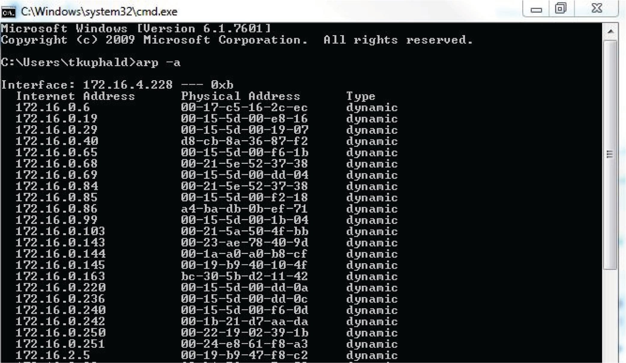
Every node running the ARP protocol on a digital network maintains a table of equivalent addresses, MAC to IP. This table is called the ARP cache, the contents of which may be displayed by running the following command on the device’s command-line interface:
arp -a
The arp -a command instructs the machine to print all (-a) ARP cache entries to the screen for your viewing. This, of course, only displays what that machine happens to know at that time. If the ARP cache has not been updated recently, addressing data found in the ARP cache may be out of date or even missing. Here is a partial screenshot of the arp -a command run on a Microsoft Windows computer, showing each IP (“internet”) address in the ARP cache and its corresponding MAC (“physical”) address:
One way to update the ARP cache on a machine with a command-line interface is to first issue a broadcast ping request. Responses from active nodes on the network will populate the machine’s ARP cache with address information, after which you may run the arp -a command to display those cache entries.
DNS
The acronym DNS actually stands for two related things: Domain Name System and Domain Name Server. The first meaning of “DNS” refers to the system of exchanging numerical IP addresses with alphanumeric Uniform Resource Locators (URLs) which are easier for human beings to remember. When you use web browser software to navigate to a web site on the Internet, you have the option of entering the URL name of that site (e.g. www.google.com) or a numerical IP address (e.g. 75.125.53.104). Special computers connected to the Internet called Domain Name Servers, and Domain Name Resolvers (DNRs) use the Address Resolution Protocol (ARP) to convert your target web site name to its actual IP address so that a connection may be made between that computer and yours.
ICANN, the same organization responsible for allotting IP addresses, also maintains databases for all registered domain names.
Command-line diagnostic utilities
In addition to ping and arp, another utility program useful for troubleshooting network connections from a Microsoft Windows computer’s command line interface is ipconfig. When executed, ipconfig returns a listing of all available (configured and operating) network interfaces on that computer:

The equivalent command for UNIX operating systems is ifconfig, shown in this screenshot:
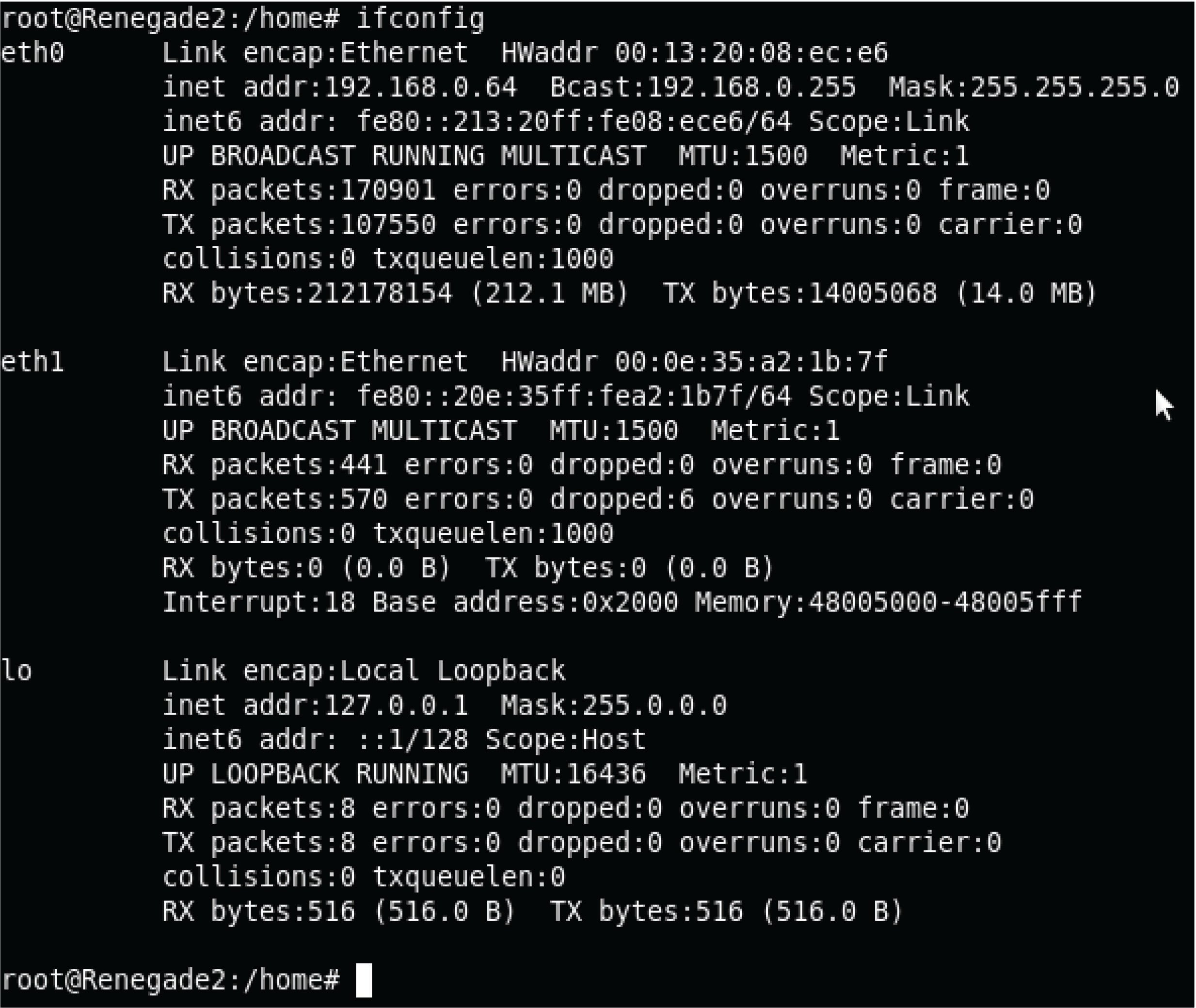
Some of the more interesting details contained in the output from ifconfig are the IPv6 addresses (in addition to IPv4 addresses), Ethernet MAC addresses (listed as “hardware addresses” or HWaddr), Ethernet performance data (e.g. number of collisions), IP performance data (e.g. number of IP packets received and transmitted), and details on the “loopback” address (IPv4 127.0.0.1 or IPv6 ::1).
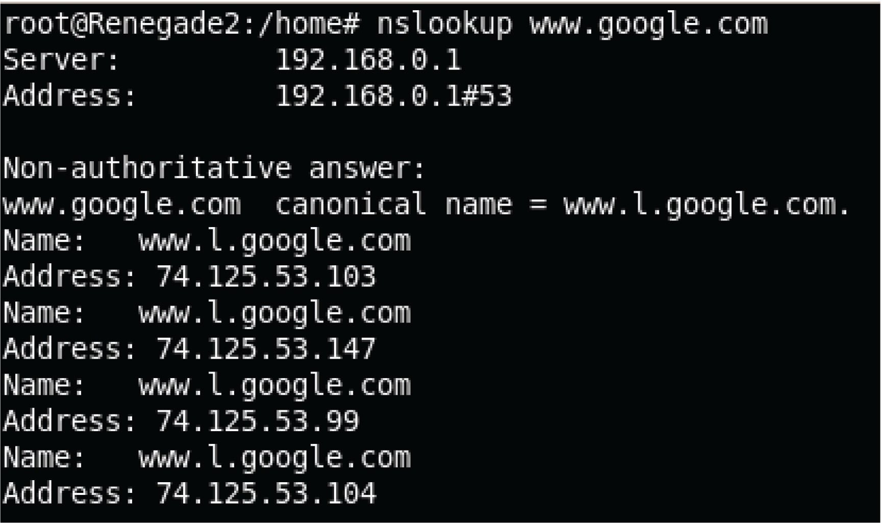
A utility intended to reveal the DNS name of a computer given its IP address, or visa versa, is nslookup. The same command works on Microsoft Windows and UNIX operating systems alike. Here, we see the UNIX version used to identify four IP addresses of the popular Google search engine web site, followed by the Microsoft Windows version:

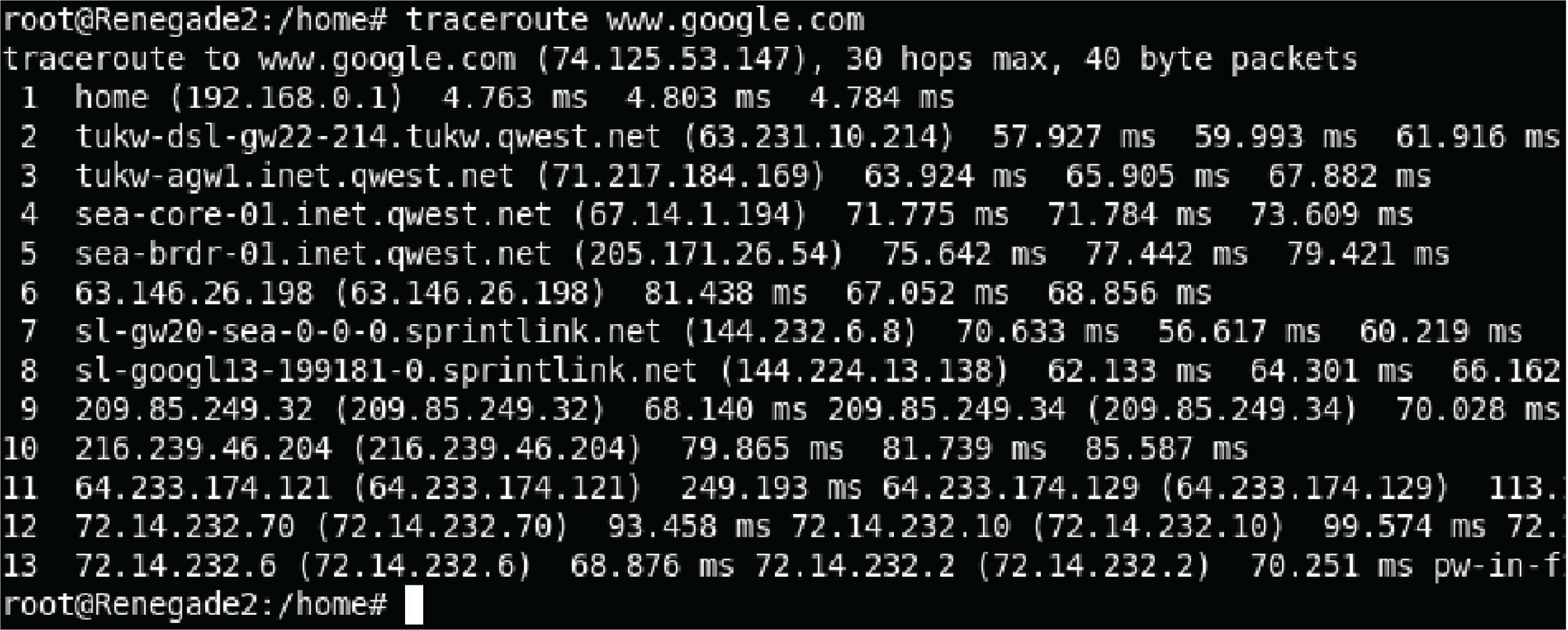
Another utility used to explore network connections is traceroute (spelled tracert on Microsoft Windows operating systems). This utility sends a test packet to the designated destination address, returning information on all the “hops” the IP packet takes between computers along the network to reach its destination and the amount of time taken to make the trip. Execution of traceroute on a UNIX computer and tracert on a Microsoft Windows computer are shown here: