 Facebook
 Google
 GitHub
 Linkedin
The HART Digital/Analog Hybrid Standard
A technological advance introduced in the late 1980’s was HART, an acronym standing for Highway Addressable Remote Transmitter. The purpose of the HART standard was to create a way for instruments to digitally communicate with one another over the same two wires used to convey a 4-20 mA analog instrument signal. In other words, HART is a hybrid communication standard, with one variable (channel) of information communicated by the analog value of a 4-20 mA DC signal, and another channel for digital communication whereby many other variables could be communicated using pulses of current to represent binary bit values of 0 and 1. Those digital current pulses are superimposed upon the analog DC current signal, such that the same two wires carry both analog and digital data simultaneously.
Basic concept of HART
Looking at a standard loop-powered (2-wire) process transmitter circuit, we see the transmitter, a DC power supply (voltage source), and usually a 250 ohm resistor to create a 1 to 5 volt signal readable by any voltage-sensing indicator, controller, or recorder:
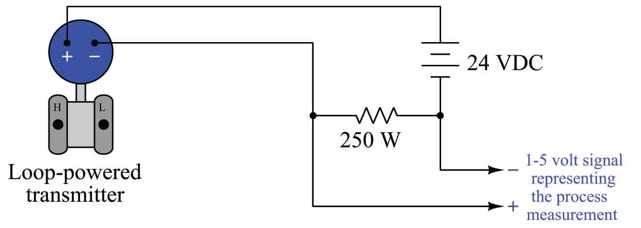
The transmitter’s primary function in this circuit is to regulate current to a value representative of the measured process variable (e.g. pressure, temperature, flow, etc.) using a range of 4 to 20 mA, while the DC voltage source provides power for the transmitter to operate. Loop-powered instruments are very common in industrial instrumentation because they allow both power and (analog) data to be conveyed on the same pair of wires.
With the advent of microprocessor-based process transmitters, it became possible for instrument technicians to digitally configure parameters inside the transmitter (e.g. range values, damping values) and also query the transmitter for self-diagnostic alarms. In order to make full use of this digital functionality, though, there had to be some way to communicate digital data to and from the process transmitter over the same two wires used to convey the 4-20 mA analog signal. Otherwise, the only way to access this rich array of digital data inside the transmitter would be to connect a communicator device to some data port located on the transmitter itself, which is inconvenient due to the nature of how these transmitters are used in industry (located in dirty places, often hard to access while carrying a personal computer or other communication device).
Thus the HART communication protocol was born to address this need. HART communicates digital data along the loop conductors in the form of AC signals (audio-frequency tones) superimposed on the 4-20 mA DC current signal. A modem built into the smart transmitter translates these AC signals into binary bits, and vice-versa. Now, instrument technicians could “talk” with the new microprocessor-based transmitters simply by connecting a HART communications device at any point along the two-wire cable, even at the far end where the cable terminates at the control system hardware (panel-mounted controller, PLC, DCS, etc.).
Being able to communicate digital data over the same wire pair as the DC power and analog signal opens a whole new range of possibilities. Now, the field-mounted transmitter can communicate self-diagnostic information, status reports, alarms, and even multiple process variables to the control system in addition to the original analog signal representing the (main) process variable. With digital communication, the only data limitation is speed (data rate), not quantity. The control system may even communicate information to the transmitter using the same digital protocol, using this digital data channel to switch between different measurement range sets, activating special features (e.g. square-root characterization, damping, etc.), automatically and remotely.
With HART, the traditional series-connected circuit configuration of transmitter, DC power supply, and resistor remains unchanged. A HART-enabled transmitter, though, is equipped with a built-in digital microcontroller managing its functions, and this miniature computer is able to send and receive digital data as AC signals (current pulses in sending mode, voltage pulses in receiving mode) superimposed on the same two wires carrying the 4 to 20 mA analog signal and DC power. Any other computer device equipped with a HART modem, the necessary configuration software, and an appropriate device description for that particular instrument may communicate with the HART transmitter if connected in parallel with the transmitter’s loop power terminals:
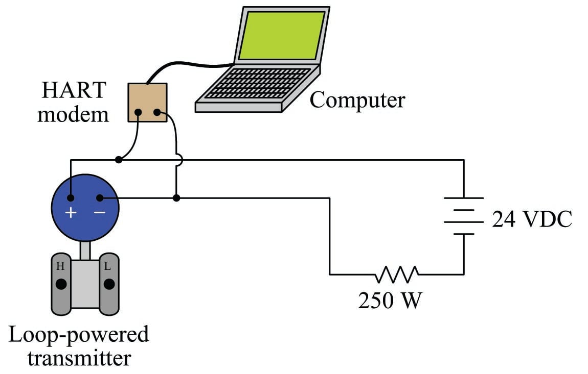
This external computer – through the use of HART data transmission – now has the ability to monitor details of the transmitter’s operation, configure the transmitter, update its measurement ranges, and perform a host of additional functions.
The connection between the HART modem and the HART-enabled transmitter need not be made directly at the transmitter’s terminals. Any set of points in the circuit electrically parallel to the transmitter’s terminals are permissible as connection points for the HART modem. This flexibility is a great advantage in loop circuits spanning long distances, enabling the technician to connect their HART configuration equipment at the most physically convenient location:

A convenient alternative to a personal computer and HART modem is a special hand-held device called a HART communicator. Two different models of HART communicator are shown in the following photographs, a Rosemount model 268 on the left and an Emerson model 375 on the right:


HART communicators are battery-powered, portable devices built specifically for configuring HART-enabled field instruments. Like personal computers, they must be updated with DD files to be able to communicate with the latest models of HART-enabled field instruments.
Perhaps the single greatest disadvantage of HART data communication is its slow speed. Not only is the bit rate slow by modern standards – only 1200 bits per second – but the encoding of HART data is laden with “overhead” bits required to synchronize devices, specify device addresses on a network, check for errors, and other functions necessary for making HART a reliable data-communications protocol. As a result, the typical time required for a complete HART transaction (one device requesting data, and the other device replying) is half a second! This means on average no more than two complete messages per second may be communicated by HART. This limits the use of HART data communication to non-routine purposes (e.g. error messages sent by field instruments, range changes made by technicians) rather than continuous process measurement and control in all but the slowest process applications.
HART technology has breathed new life into the venerable 4-20 mA analog instrumentation signal standard. It has allowed new features and capabilities to be added on to existing analog signal loops without having to upgrade wiring or change all the instruments in the loop. Some of the features of HART are listed here:
- Diagnostic data may be transmitted by the field device (self-test results, out-of-limit alarms, preventive maintenance alerts, etc.)
- Field instruments may be re-ranged remotely through the use of HART communicators
- Technicians may use HART communicators to force field instruments into different “manual” modes for diagnostic purposes (e.g. forcing a transmitter to output a fixed current so as to check calibration of other loop components, manually stroking a valve equipped with a HART-capable positioner)
- Field instruments may be programmed with identification data (e.g. tag numbers corresponding to plant-wide instrument loop documentation)
It should be mentioned that HART communication over 4-20 mA signal wires is a legacy technology. At the time of this writing (2011), HART protocol is still the most popular form of wired digital field instrument communication in industrial use. However, more modern digital standards such as Profibus and FOUNDATION Fieldbus deliver all the benefits of HART technology and more. It seems that wired-HART will remain in wide industrial use for many years to come, but it is really just the beginning of digital field instrument technology and does not represent the state of the art. For more information regarding modern “fieldbus” digital instrumentation, refer to chapter 16 on the FOUNDATION Fieldbus standard beginning on page .
An important addition to the HART standard introduced with version 7 is wireless (radio) communication capability. This portion of the standard describes how HART data may be communicated via radio waves instead of audio-frequency AC signal bursts superimposed on DC signal wires. Here, HART is the sole method of exchanging process data between field instruments rather than a secondary method to a 4-20 mA DC analog signal. Communicating over radio waves eliminates the theoretical speed barrier faced by wired-HART (1200 bits per second) while still permitting HART-compliant computer software and field communicator devices to work with these wireless instruments.
HART physical layer
The HART standard was developed with existing installations in mind. The signals had to be robust enough to travel over twisted-pair cables of very long length and unknown characteristic impedance. This meant that the data communication rate for the digital data had to be very slow, even by 1980’s standards, in order to avoid problems created by reflections along unterminated cabling. The HART standard is concerned only with three layers of the OSI Reference model: layer 1 (FSK modulation, \(\pm\) 0.5 mA transmitter signaling), layer 2 (Master-slave arbitration, data frame organization), and layer 7 (specific commands to read and write device data). Layers 3 through 6 of the OSI model are irrelevant to the HART standard.
Digital data is encoded in HART using the Bell 202 modem standard: two audio-frequency “tones” (1200 Hz and 2200 Hz) are used to represent the binary states of “1” and “0,” respectively, transmitted at a rate of 1200 bits per second. This is known as frequency-shift keying, or FSK. The physical representation of these two frequencies is an AC current of 1 mA peak-to-peak superimposed on the 4-20 mA DC signal. Thus, when a HART-compatible device “talks” digitally on a two-wire loop circuit, it produces tone bursts of AC current at 1.2 kHz and 2.2 kHz. The receiving HART device “listens” for these AC current frequencies and interprets them as binary bits. The following photograph shows a HART waveform captured by a digital oscilloscope:

Each “1” bit in this HART waveform is a single cycle of 1200 Hz tone, while each “0” bit is a double-cycle of 2200 Hz tone. The waveform shown here is an alternating series of “1” and “0” bits.
An important consideration in HART current loops is that the total loop resistance (precision resistor values plus wire resistance) must fall within a certain range: 250 ohms to 1100 ohms. Most 4-20 mA loops (containing a single 250 ohm resistor for converting 4-20 mA to 1-5 V) measure in at just over 250 ohms total resistance, and work quite well with HART. Even loops containing two 250 ohm precision resistors meet this requirement. Where technicians often encounter problems is when they set up a loop-powered HART transmitter on the test bench with a lab-style power supply and no 250 ohm resistor anywhere in the circuit:

The HART transmitter may be modeled as two parallel current sources: one DC and one AC. The DC current source provides the 4-20 mA regulation necessary to represent the process measurement as an analog current value. The AC current source turns on and off as necessary to “inject” the 1 mA P-P audio-frequency HART signal along the two wires. Inside the transmitter is also a HART modem for interpreting AC voltage tones as HART data packets. Thus, data transmission takes place through the AC current source, and data reception takes place through a voltage-sensitive modem, all inside the transmitter, all “talking” along the same two wires that carry the DC 4-20 mA signal.
For ease of connection in the field, HART devices are designed to be connected in parallel with each other. This eliminates the need to break the loop and interrupt the DC current signal every time we wish to connect a HART communicator device to communicate with the transmitter. A typical HART communicator may be modeled as an AC voltage source (along with another HART voltage-sensitive modem for receiving HART data). Connected in parallel with the HART transmitter, the complete circuit looks something like this:

With all these sources in the same circuit, it is advisable to use the Superposition Theorem for analysis. This involves “turning off” all but one source at a time to see what the effect is for each source, then superimposing the results to see what all the sources do when all are working simultaneously.
We really only need to consider the effects of either AC source to see what the problem is in this circuit with no loop resistance. Consider the situation where the transmitter is sending HART data to the communicator. The AC current source inside the transmitter will be active, injecting its 1 mA P-P audio-frequency signal onto the two wires of the circuit. The AC voltage source in the communicator will disconnect itself from the network, allowing the communicator to “listen” to the transmitter’s data.
To apply the Superposition Theorem, we replace all the other sources with their own equivalent internal resistances (voltage sources become “shorts,” and current sources become “opens”). The HART communicator will be modeled as an “open” even though it is technically a voltage source because it must turn itself off (i.e. switch to high-impedance mode) in order for any field device to communicate to it:

The HART communicator is “listening” for those audio tone signals sent by the transmitter’s AC source, but it “hears” nothing because the DC power supply’s equivalent short-circuit prevents any significant AC voltage from developing across the two wires. This is what happens when there is no loop resistance: no HART device is able to receive data sent by any other HART device.
The solution to this dilemma is to install a resistance of at least 250 ohms but not greater than 1100 ohms between the DC power source and all other HART devices, like this:

Loop resistance must be at least 250 ohms to allow the 1 mA P-P AC signal to develop enough voltage to be reliably detected by the HART modem in the listening device. The upper limit (1100 ohms) is not a function of HART communication so much as it is a function of the DC voltage drop, and the need to maintain a minimum DC terminal voltage at the transmitter for its own operation. If there is too much loop resistance, the transmitter will become “starved” of voltage and act erratically. In fact, even 1100 ohms of loop resistance may be too much if the DC power supply voltage is modest.
Loop resistance is also necessary for the HART transmitter to receive data signals transmitted by the HART communicator. If we analyze the circuit when the HART communicator’s voltage source is active (replacing the DC power supply with a short and the transmitter current sources with opens), we get this result:

Without the loop resistance in place, the DC power supply would “short out” the communicator’s AC voltage signal just as effectively as it shorted out the transmitter’s AC current signal. The presence of a loop resistor in the circuit prevents the DC power supply from “loading” the AC voltage signal by the communicator. This AC voltage is seen in the diagram as being directly in parallel with the transmitter, where its internal HART modem receives the audio tones and processes the data packets.
Manufacturers’ instructions generally recommend HART communicator devices be connected directly in parallel with the HART field instrument, as shown in the previous schematic diagrams. However, it is also perfectly valid to connect the communicator device directly in parallel with the loop resistor like this:

Connected directly in parallel with the loop resistor, the communicator is able to receive transmissions from the HART transmitter just fine, as the DC power source acts as a dead short to the AC current HART signal and passes it through to the transmitter.
This is nice to know, as it is often easier to achieve an alligator-clip connection across the leads of a resistor than it is to clip in parallel with the loop wires when at a terminal strip or at the controller end of the loop circuit.
HART multidrop mode
The HART standard also supports a mode of operation that is totally digital, and capable of supporting multiple HART instruments on the same pair of wires. This is known as multidrop mode, where field instruments are slaves and the communicator (or control system) is the master.
Every HART instrument has an address number, which is typically set to a value of zero (0). A network address is a number used to distinguish one device from another on a broadcast network, so messages broadcast across the network may be directed to specific destinations. When a HART instrument operates in digital/analog hybrid mode, where it must have its own dedicated wire pair for communicating the 4-20 mA DC signal between it and an indicator or controller, there is no need for a digital address. An address becomes necessary only when multiple devices are connected to the same network wiring, and there arises a need to digitally distinguish one device from another on the same network.
This is a functionality the designers of HART intended from the beginning, although it is rarely used in industry. Multiple HART instruments may be connected directly in parallel with one another along the same wire pair, and information exchanged between those instruments and a host system, if the HART address numbers are set to non-zero values (between 1 and 15):

Setting an instrument’s HART address to a non-zero value is all that is necessary to engage multidrop mode. The address numbers themselves are irrelevant, as long as they fall within the range of 1 to 15 and are unique within that network. Once a HART instrument is configured for multi-drop mode (i.e. given a non-zero HART address), its current becomes fixed at 4 mA and no longer varies with the process variable measurement.
The major disadvantage of using HART instruments in multidrop mode is its slow speed. Due to HART’s slow data rate (1200 bits per second), it may take several seconds to access a particular instrument’s data on a multidropped network. For some applications such as temperature measurement, this slow response time may be acceptable. For inherently faster processes such as liquid flow control, it would not be nearly fast enough to provide up-to-date information for the control system to act upon.
HART multi-variable transmitters and burst mode
Some “smart” instruments have the ability to report multiple process variables. A good example of this is Coriolis-effect flowmeters, which by their very nature simultaneously measure the density, flow rate, and temperature of the fluid passing through them. A single pair of wires can only convey one 4-20 mA analog signal, but that same pair of wires may convey multiple digital signals using HART protocol.
If the host system receiving the transmitter’s signal(s) is HART-ready, it may digitally poll the transmitters for all variables. If, however, the host system does not “talk” using the HART protocol, some other means must be found to decode the wealth of digital data digitally offered by the multi-variable transmitter. One such device is Rosemount’s model 333 HART “Tri-Loop” demultiplexer shown in the following photograph:

This device uses a feature of HART called burst mode where one HART instrument repeatedly transmits information rather than waiting to be polled by a master HART device (such as a control system or a hand-held communicator). The Rosemount 333 receives these bursts of data, converting as many as three digitally-encoded HART variables into independent 4-20 mA analog output signals, which any suitable analog indicator or controller device may then receive.
It should be noted that the same caveat applicable to multidrop HART systems (i.e. slow speed) applies to multi-variable HART communication as well. Even though burst mode eliminates the need for master-device communications and therefore occupies less time than normal (polled) HART communication, typical wait times for HART data may still be too long for some industrial process applications. Typical HART burst rate is approximately three HART “telegram” packets per second, as opposed to two complete transmissions per second in the case of polled HART where the master requests data and the slave replies. If we configure a process transmitter to burst-communicate three different variables, for example, the update rate for each one of those variables will be approximately once per second (three variables communicated at a total rate of three HART telegrams per second), which is simply too slow for many industrial applications (e.g. closed-loop liquid flow control). In applications where speed is not a concern, however, HART communication is a very practical solution for acquiring multiple channels of data from one instrument over a single pair of wires.
