 Facebook
 Google
 GitHub
 Linkedin
Ratio Control
Most people reading this book have likely had the experience of adjusting water temperature using two hand valves as they took a shower: one valve controlling the flow of hot water and the other valve controlling the flow of cold water. In order to adjust water temperature, the proportion of one valve opening to the other must be changed. Increasing or decreasing total water flow rate without upsetting the outlet temperature is a matter of adjusting both valves in the same direction, maintaining that same proportion of hot to cold water flow.
Although you may not have given it much thought while taking your shower, you were engaged in a control strategy known as ratio control, where the ratio of one flow rate to another is controlled for some desired outcome. Many industrial processes also require the precise mixing of two or more ingredients to produce a desired product. Not only do these ingredients need to be mixed in proper proportion, but it is usually desirable to have precise control over the total flow rate as well.
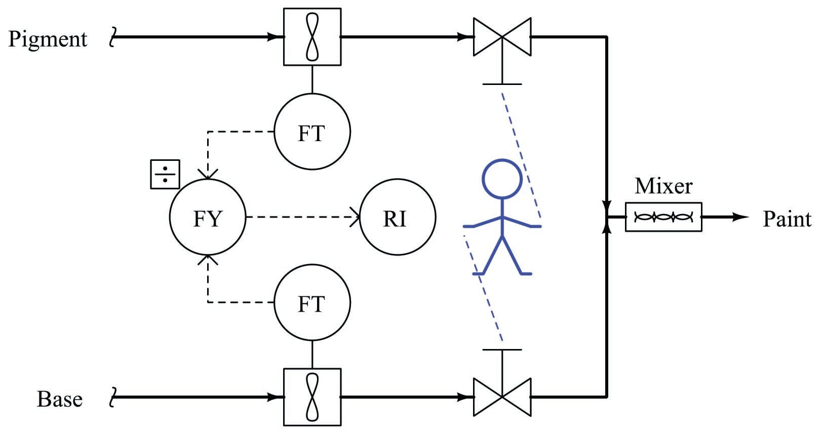
A simple example of ratio control is in the production of paint, where a base liquid must be mixed with one or more pigments to achieve a desired consistency and color. A manually controlled paint mixing process, similar to the hot and cold water valve “process” in some home showers, is shown here. Two flowmeters, a ratio calculating relay, and a display provide the human operator with a live measurement of pigment-to-base ratio:
One alteration we could make to this mixing system is to link the two manual control valve handles together in such a way that the ratio of base to pigment was mechanically established. All the human operator needs to do now is move the one link to increase or decrease mixed paint production:
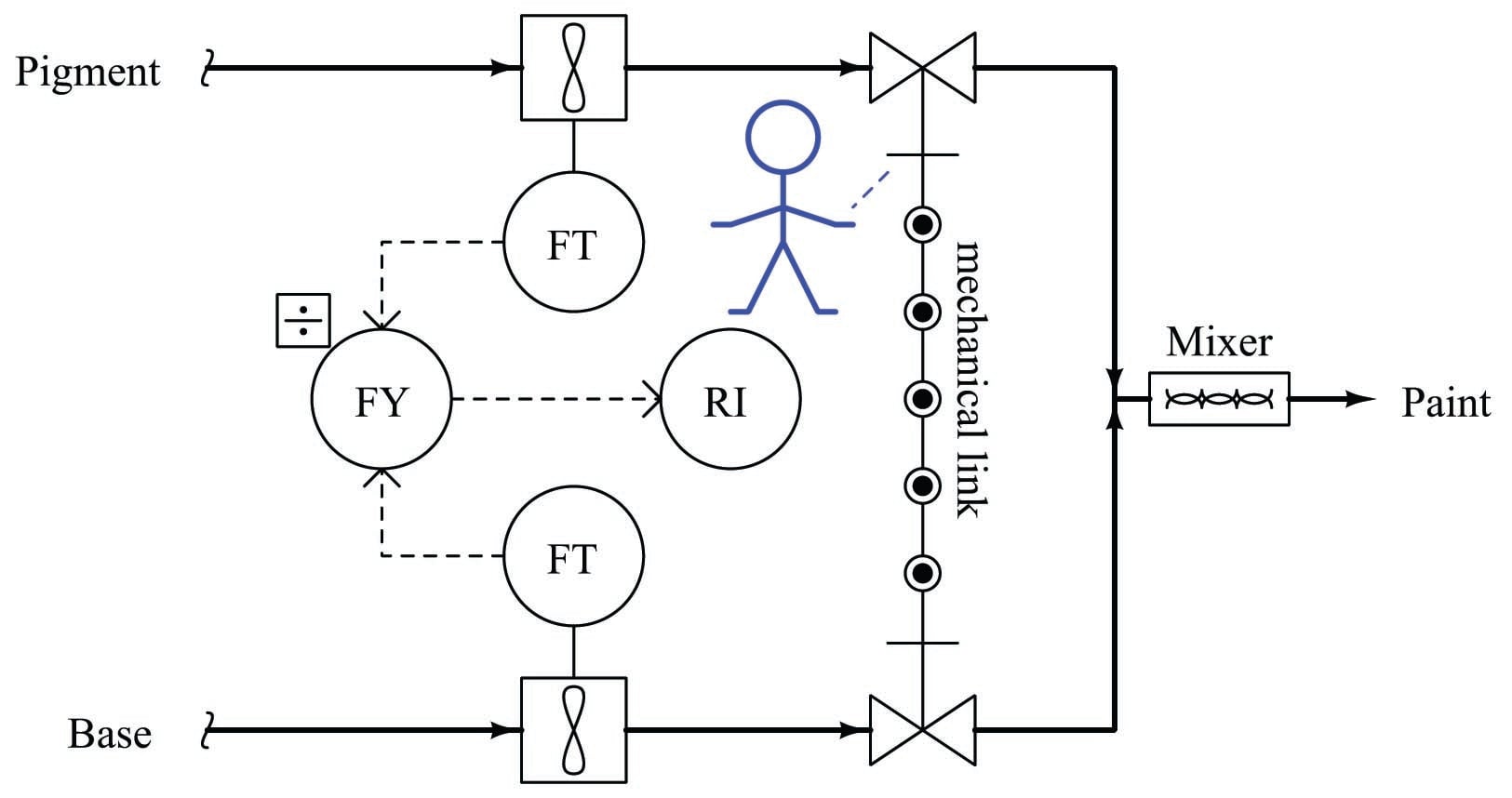
Adjusting the pigment-to-base ratio is now a matter of adjusting the linkage ratio, a task most likely performed by a mechanic or someone else skilled in the alignment of mechanical linkages. The convenience of total flow adjustment gained by the link comes at the price of inconvenient ratio adjustment.
Mechanical link ratio-control systems are commonly used to manage simple burners, proportioning the flow rates of fuel and air for clean, efficient combustion. A photograph of such a system appears here, showing how the fuel gas valve and air damper motions are coordinated by a single rotary actuator:
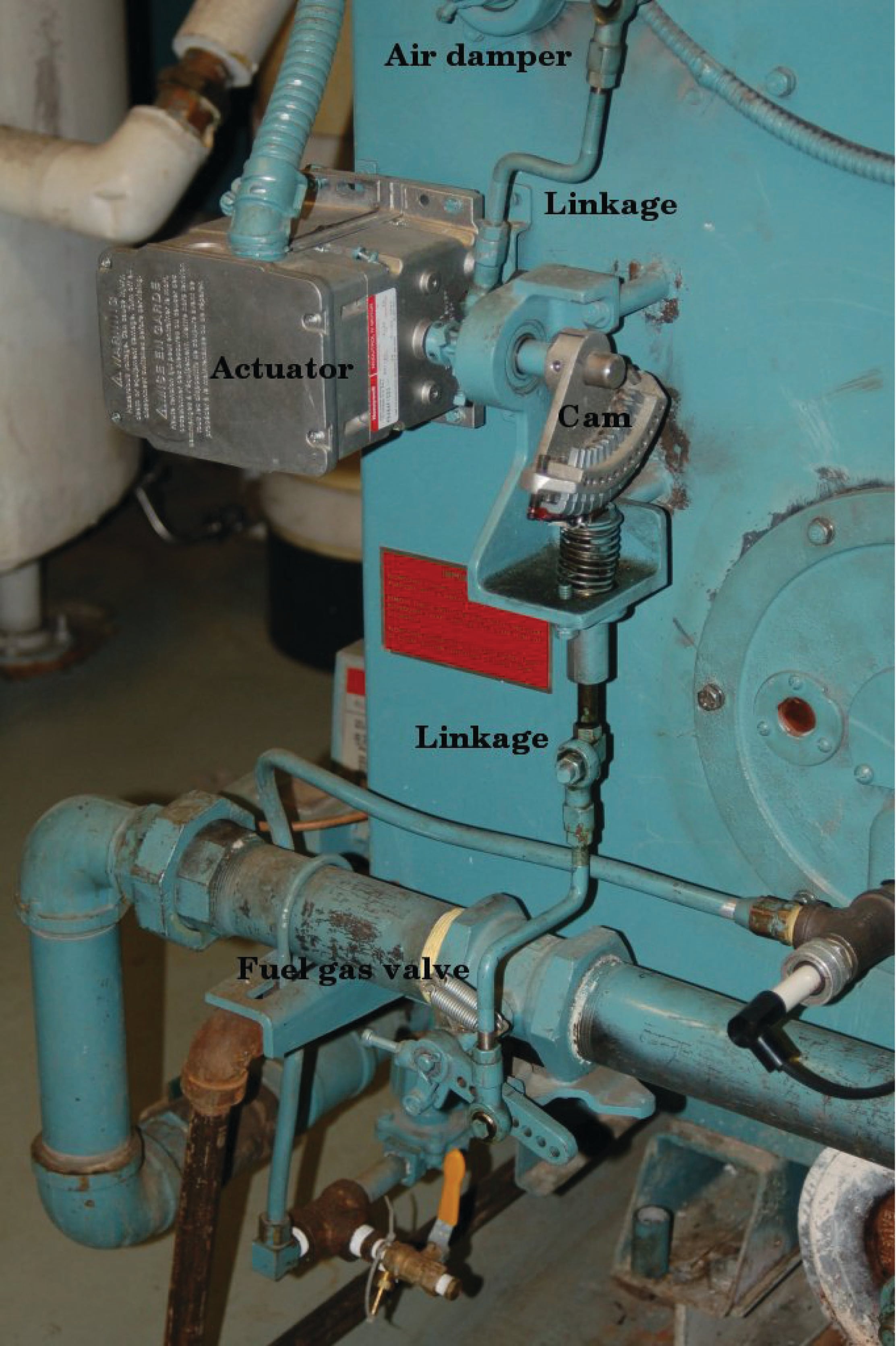
As you can see in this photo, the fuel gas valve is actuated by means of a cam, allowing precise “tuning” of the valve characteristics for consistent fuel/air ratio across a wide range of firing rates. Making ratio adjustments in such a linkage system is obviously a task for a skilled mechanic or technician.
A more automated approach to the general problem of ratio control involves the installation of a flow control loop on one of the lines and a flow-sensing transmitter on the other line. The signal coming from the uncontrolled flow transmitter becomes the setpoint for the flow control loop:
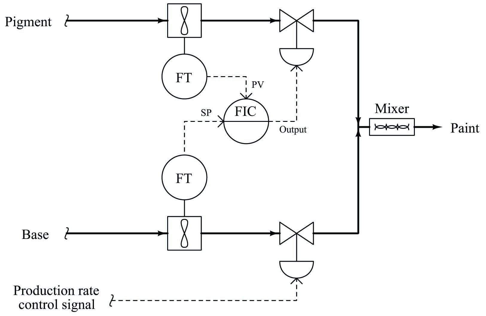
Here, the flow transmitter on the uncontrolled line measures the flow rate of base, sending a flow rate signal to the pigment flow controller which acts to match flow rates. If the calibrations of each flow transmitter are precisely equal to one another, the ratio of pigment to base will be 1:1 (equal). The flow of base liquid into the mixing system is called a wild flow or wild variable, since this flow rate is not controlled by the ratio control system. The only purpose served by the ratio control system is to match the pigment flow rate to the wild (base) flow rate, so the same ratio of pigment to base will always be maintained regardless of total flow rate. Thus, the flow rate of pigment will be held captive to match the “wild” base flow rate, which is why the controlled variable in a ratio system is sometimes called the captive variable (in this case, a captive flow).
As with the mechanically-linked manual ratio mixing system, this ratio control system provides convenient total flow control at the expense of convenient ratio adjustment. In order to alter the ratio of pigment to base, someone must re-range one or more flow transmitters. To achieve a 2:1 ratio of base to pigment, for example, the base flow transmitter’s range would have to be double that of the pigment flow transmitter. This way, an equal percentage of flow registered by both flow transmitters (as the ratio controller strives to maintain equal percentage values of flow between pigment and base) would actually result in twice the amount of base flow than pigment flow.
We may incorporate convenient ratio adjustment into this system by adding another component (or function block) to the control scheme: a device called a signal multiplying relay (or alternatively, a ratio station). This device (or computer function) takes the flow signal from the base (wild) flow transmitter and multiplies it by some constant value (\(k\)) before sending the signal to the pigment (captive) flow controller as a setpoint:
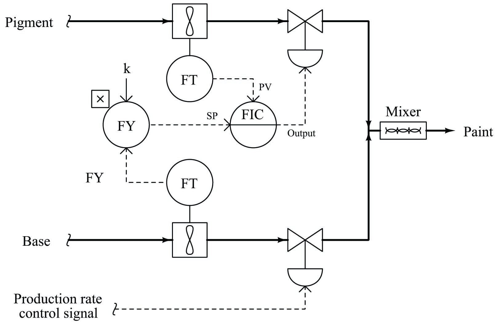
With identical flow range calibrations in both flow transmitters, this multiplying constant \(k\) directly determines the pigment-to-base ratio (i.e. the ratio will be 1:1 when \(k=1\); the ratio will be 2:1 when \(k=2\), etc.). If the \(k\) value is easily adjusted by a human operator, mixing ratio becomes a very simple parameter to change at will, just as the total production rate is easy to adjust by moving the base flow control valve.
Another example of ratio control at work is in a process whereby hydrocarbon gases (usually methane) are converted into hydrogen gas and carbon dioxide gas. This is known as the steam-hydrocarbon reforming process, and it is one of the more popular ways of generating hydrogen gas for industrial use. The overall reaction for this process with methane gas (CH\(_{4}\)) and steam (H\(_{2}\)O) as the reactants is as follows996:
\[\hbox{CH}_4 + 2\hbox{H}_2\hbox{O} \to 4\hbox{H}_2 + \hbox{CO}_2\]
This is an endothermic chemical reaction, which means a net input of energy is required to make it happen. Typically, the hydrocarbon gas and steam are mixed together in a heated environment in the presence of a catalyst (to reduce the activation energy requirements of the reaction). This usually takes the form of catalyst-packed metal tubes inside a gas-fired furnace. It is important to control the proportion of gas to steam flow into this process. Too much hydrocarbon gas, and the result will be “coking” (solid hydrocarbon deposits) inside the heated tubes and on the surface of the catalyst beads, decreasing the efficiency of the process over time. Too much steam and the result is wasted energy as unreacted steam simply passes through the heater tubes, absorbing heat and carrying it away from the catalyst where it would otherwise do useful work.
One way to achieve the proper ratio of hydrocarbon gas to steam flow is to install a normal flow control loop on one of these two reactant feed lines, then use that process variable (flow) signal as a setpoint to a flow controller installed on the other reactant feed line. This way, the second controller will maintain a proper balance of flow to proportionately match the flow rate of the other reactant. An example P&ID is shown here, where the methane gas flow rate establishes the setpoint for steam flow control:
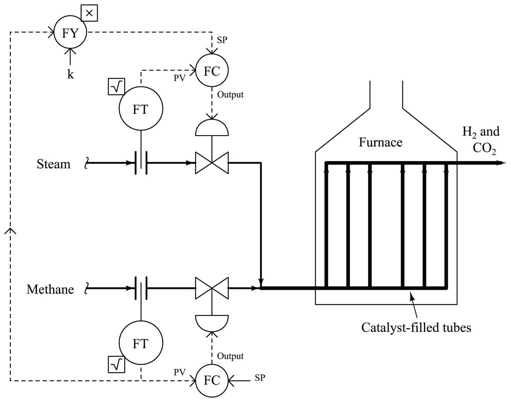
Note how the methane gas flow transmitter signal goes both to the methane flow controller and to a multiplying relay that multiplies this signal by a constant value (\(k\)) before passing it on to the steam flow controller as a setpoint. This \(k\) value sets the ratio of steam flow to methane flow. Although this might appear to be a cascade control system at first glance, it is actually quite different. In a cascade system, the output of one controller becomes the setpoint for another. Here in a ratio control system, the process variable of one controller becomes the setpoint for another, such that two process variables remain in constant proportion (ratio) to one another.
If the two flow transmitters are compensated to measure mass flow, the ideal value of \(k\) should be set such that two molecules of steam vapor (H\(_{2}\)O) enter the reforming furnace for every one molecule of methane (CH\(_{4}\)). With a 2-to-1 molecular ratio of steam to methane (2 moles of steam per one mole of methane), this equates to a 9-to-4 mass flow ratio once the formula weights of steam and methane are calculated997. Thus, if the methane and gas flowmeters are calibrated for equal mass flow ranges, the ideal value for \(k\) should be \({9 \over 4}\), or 2.25. Alternatively, the flow transmitter calibrations could be set in such a way that the ideal ratio is intrinsic to those transmitters’ ranges (i.e. the methane flow transmitter has 2.25 times the mass flow range of the steam flow transmitter), with \(k\) set to an ideal value of 1. This way a 9:4 ratio of methane mass flow to steam mass flow will result in equal percentage output values from both flow transmitters. In practice, the value for \(k\) is set a bit higher than ideal, in order to ensure just a little excess steam to guard against coking inside the reaction heater tubes998.
We could add another layer of sophistication to this ratio control system by installing a gas analyzer at the outlet of the reaction furnace designed to measure the composition of the product stream. This analyzer’s signal could be used to adjust the value of \(k\) so the ratio of steam to methane would automatically vary to ensure optimum production quality even if the feedstock composition (i.e. percentage concentration of methane in the hydrocarbon gas input) changes:
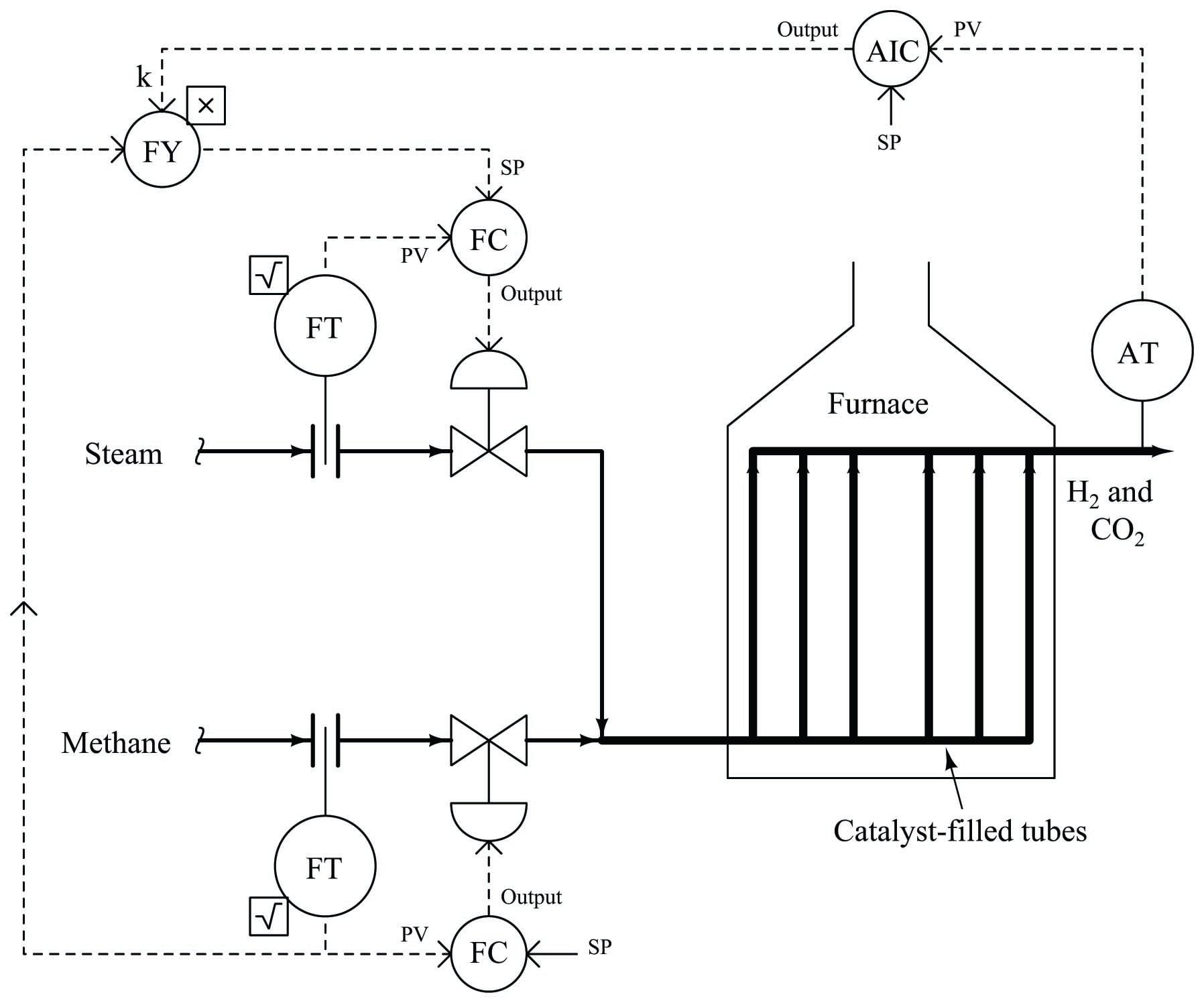
As we saw before, pure methane feed requires a 9-to-4 steam-to-methane mass flow ratio for the desired reaction to be stoichiometrically balanced. This mass ratio, however, is not balanced for hydrocarbons other than methane. Ethane (C\(_{2}\)H\(_{6}\)) processed in the same way requires a 12-to-5 steam-to-ethane mass flow ratio. Propane (C\(_{3}\)H\(_{8}\)) requires a 26-to-11 steam-to-propane mass flow ratio. If the hydrocarbon feed to the reforming furnace varies in composition, the steam flow ratio (\(k\)) must change accordingly for efficient reaction.
